Do you have a question about the FAAC E720 and is the answer not in the manual?
Essential safety guidance for installation and use, highlighting potential harm.
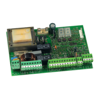
Details the connection points for inputs and power on terminal block J12.
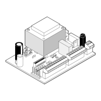
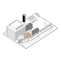
Identifies key components like LEDs, connectors, and switches on the main board.
Detailed descriptions of the control board's components and connectors.
Lists electrical, environmental, and operational parameters of the E720 unit.
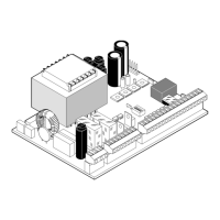
Illustrates the main power and component connections to the control board.
Explains the functional differences of safety devices during opening and closing.
Details addressing, status LEDs, and storage procedures for BUS-2EASY photocells.
Illustrates connection diagrams for various configurations of traditional photocells.
Visual guides for connecting various combinations of opening, closing, and combined photocells.
Diagrams showing how to connect systems with or without safety and stop devices.
Steps to enter and navigate the initial programming level.
Details on configuring logic, pause times, and default settings.
Configuration of motor power, opening, and closing speeds.
Settings for slowing parameters and exiting programming mode.
Procedure to enter and navigate the advanced programming level.
Settings for take-off power, preflashing, photocell logic, and encoder.
Configuration for partial opening, time-out, output activation, and edge safety devices.
Settings for motor lock operation and defining functions for OPEN B and STOP inputs.
Programming for cycle counters, maintenance requests, and exiting programming.
Overview of radio code storage systems and procedures.
Step-by-step guide for programming DS and SLH type radio controls.
Instructions for LC/RC controls, remote storage, and deleting all stored codes.
Guide to understanding the meaning of various LEDs on the control board.
Details the operational states indicated by the POWER LED.
Detailed steps for correctly positioning limit switch magnets.
Clarifies which magnet shape corresponds to opening and closing limits.
Step-by-step guide for performing the essential system setup routine.
Explains alarm conditions, ERROR LED behavior, and lists common alarm codes.
Lists error codes, their meanings, and how they are indicated.
Details the operational behavior of the 'E' logic for various system states.
Explains the behavior of EP and A logic modes for different system statuses.
Details the operational characteristics of the A1 logic mode.
Describes the operational behavior of AP and A+ logic modes.
Explains the operational characteristics of S and SP logic modes.
| Brand | FAAC |
|---|---|
| Model | E720 |
| Category | Control Panel |
| Language | English |