/ SAFE
ENGLISH
4.1 BUS-2EASY PHOTOCELLS
This board is equipped with a BUS-2EASY circuit that can
be used to easily connect a high number of auxiliary BUS-
2EASY devices to the safety device (e.g. up to 16 pairs of
photocells), appropriately programmed, using only two
cables without polarity.
Before connecting the photocells, it is advisable to select
the type of operation (Fig. 3) on the basis of the area of
movement the cells must protect and to position the dip
switches on both the transmitter and receiver (see Fig. 4)
as in Tab. 1.
4.1.1 ADDRESSING BUS-2EASY PHOTOCELLS
It is important to give both the transmitter
and the receiver the same address.
Ensure that there are not two or more pho-
tocell pairs with the same address.
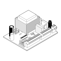
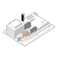
If no BUS-2EASY accessory is used, leave the
BUS-2EASY connector (J12 - fig. 1) free.
Dip1 Dip2 Dip3 Dip4 Re. Type
OFF OFF OFF OFF
B
OPENING
Max. 6 pairs
OFF OFF OFF ON
OFF OFF ON OFF
OFF OFF ON ON
OFF ON ON OFF
OFF ON ON ON
ON OFF OFF OFF
A
CLOSING
Max. 7 pairs
ON OFF OFF ON
ON OFF ON OFF
ON OFF ON ON
ON ON OFF OFF
ON ON OFF ON
ON ON ON OFF
OFF ON OFF OFF
C
OPENING and
CLOSING
Max. 2 pairs
OFF ON OFF ON
ON ON ON ON / OPEN PULSE
Tab. 1 - Addressing BUS-2EASY photocells
4.1.2 STORING BUS-2EASY ACCESSORIES
It is possible to add BUS-2EASY photocells to the system at
any time, simply by following the procedure below:
Install and programme the accessories with the re-
quired address (see par. 4.1.1).
Cut off power to the board.
Connect both cables of the BUS-2EASY accessories to
the red terminal block J12 (polarity irrelevant).
Power the board.
Quickly press the SETUP push-button (SW4) once to
register the accessories. Check the operation of the
installed BUS-2EASY devices.
The board has stored the BUS-2EASY accessories.
1.
2.
3.
4.
5.
6.
Connection of 1 pair of closing photocells
with FAIL-SAFE and STOP safety device
deactivated
Connection of 1 pair of closing photocells
with FAIL-SAFE safety device
activated
Other safety
devices
Set in second level of programming
o1 = 01
Other safety
devices
Follow the instructions in the following table to check that
the BUS-2EASY connection status is efficient.
Tab. 2 - Description of BUS-2EASY led
Fixed ON
Normal activity (led on even without photo-
cells). No registered photocell engaged.
Slow
flasher
At least one registered photocell engaged
or not aligned.
Off (flash
every
2.5 secs)
BUS-2EASY line short-circuited.
Off BUS-2EASY line deactivated.
If the FAIL-SAFE safety device is
not
used,
connect the power supply of the transmit-
ters to terminals 6 and 8 of J13.
If the FAIL-SAFE safety device is uses, con-
nect the power supply of the transmitters
to OUT after setting it as appropriate (see
2nd level programming and Fig. 16).
If the FAIL-SAFE safety device is used, even the
unused safety inputs must be connected via a
shunt lead to the negative of OUT (see Fig. 16).
4.2 TRADITIONAL PHOTOCELLS