SAFE
ENGLISH
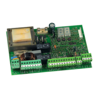
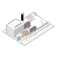
DL1 = Align-
ment
DL2 = BUS-
2EASY/Power
supply status
DS1 = Dip-
switches for
programming
A: Photocells that operate during CLOSING
B: Photocells that operate during OPENING
C: Photocells that operate during OPENING and CLOSING
Before connecting the photocells, it is advisable to select
the type of operation on the basis of the area of move-
ment that they need to protect:
Safety devices during closing: operate only during the
automated system closing movement and are there-
fore suitable for protecting the closing area from the
risk of impact.
Safety devices during opening: operate only during
the automated system opening movement and are
therefore suitable for protecting the opening area from
the risk of impact.
Safety devices during opening/closing: operate during
both the automated system opening and closing move-
ments and are therefore suitable for protecting the entire
movement area from the risk of impact.
MOTOR RELEASE
CONTACT
(Locks the motor when the
motor release handle is
operated)
4 ELECTRIC CONNECTIONS
To connect the photo-
cells and safety devices,
consult paragraph 4.2