6. Carefully wash and relubricate all bearings as
removed, and protectively wrap until ready for
use. Remove bearings with pullers designed for
this purpose, or in a manner which will not dam
-
age those bearings that will be reused.
7. When necessary to apply force to remove a
part, the use of a puller or press is preferred. In
some cases, the use of a bar or soft hammer
may be allowable.
4.2 BRAKE DRUM, HUB, AND WHEEL
BEARINGS
1. Raise the front of the vehicle with a jack and se
-
cure with jackstands of suitable capacity. Also
remove the front wheels.
2. Remove the brake drums.
WARNING: WHEN REMOVING THE BRAKE
DRUMS TAKE SUITABLE PRE
-
CAUTIONS IF THE POSSIBILITY
OF EXPOSURE TO ASBESTOS
DUST EXISTS. SEE ASBESTOS
WARNING LOCATED IN THE
FRONT OF THIS MANUAL.
FABCO ORIGINAL EQUIPMENT
BRAKE SHOES ARE NOT AS-
BESTOS BASED.
3. Remove the eight 5/8" outer drive flange
locknuts.
4. The drive flange should be loose enough to re-
move by hand. If it is not, use two 1/2"-20 bolts
in the extractor holes provided for this purpose.
See Figure 8.
5. Remove the wheel bearing locknut, washer,
and adjusting nut from the spindle. Rock the
hub in place to loosen the outer wheel bearing
cone. Remove the cone and wrap it protec
-
tively.
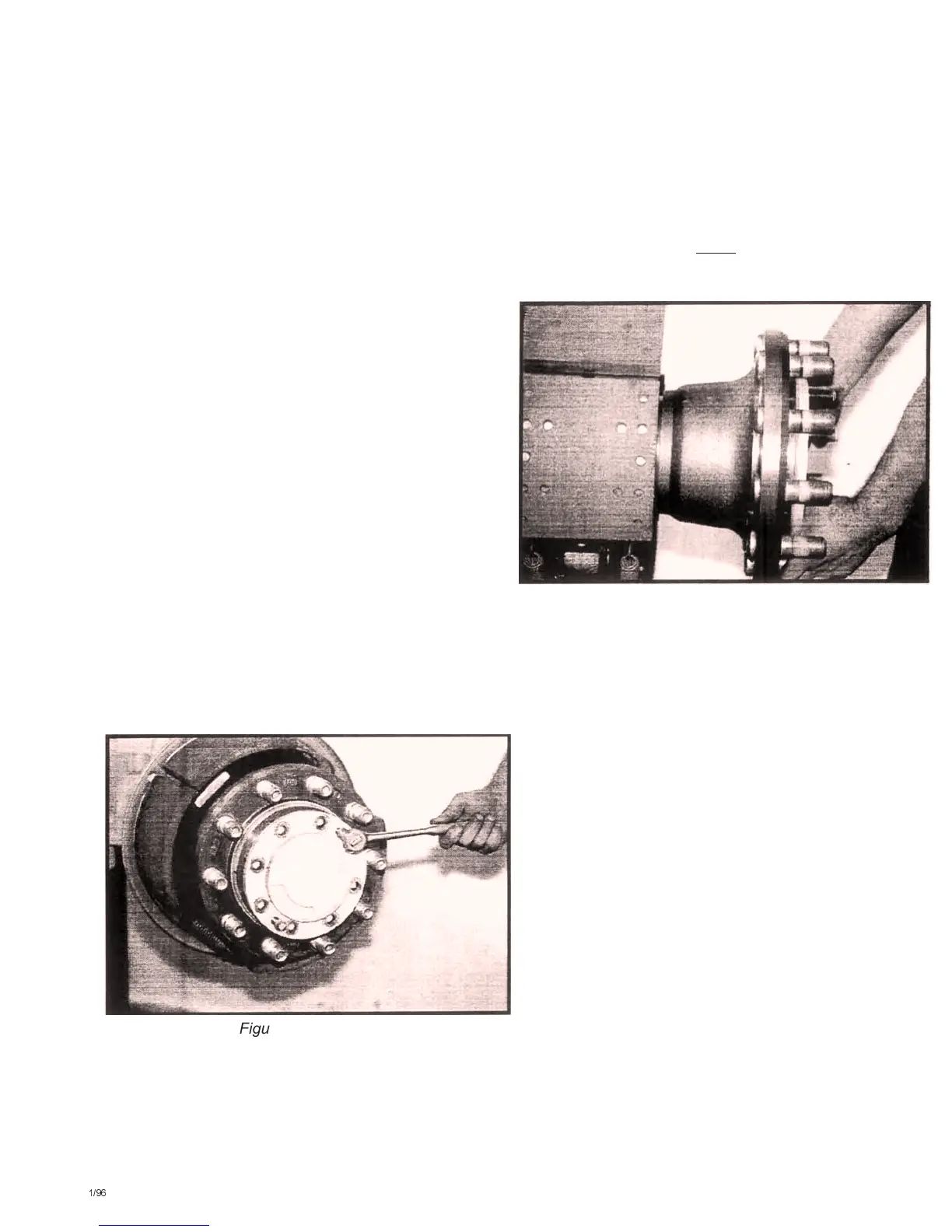
6. Remove the hub, initially attempting to pull the
assembly straight off to avoid cocking the inner
bearing cone. See Figure 9. If the cone binds
against the spindle try rocking the hub to free it,
but it may be necessary to use a pry bar under
the inner surface of the hub. (To avoid damag
-
ing the inner seal, pry against the hub only.) If
the inner bearing remains on the spindle when
the hub is removed, use a suitable puller to re
-
move it, pulling only against the bearing's race.
Alternately, tap lightly
on the race's outboard
surface with a small drift to correct its misalign
-
ment and again attempt to remove it by hand.
7. Wheel bearing cups may be removed from the
hub using a suitable puller. Pull the cup out
evenly.
NOTE: This is the limit of routine disassembly.
Brake shoes and wheel bearings may
be accessed for maintenance, but fur
-
ther disassembly may be required to
replace damaged or broken parts.
4.3 BRAKE AND WHEEL SPINDLE
1. Removal of the brake shoes will be facilitated by
turning out the 7/16" adjustment screw on the
slack adjuster to relieve tension on the S-cam
rollers. See Figure 10. Turn the screw counter
-
clockwise until the rollers rest at the lowest point
on the cam.
–12–
1/96
Figure #8
Figure #9
 Loading...