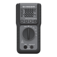
The FACOM 711B is a small, hand-held, safe, and reliable digital auto-ranging multimeter with stable performance and a novel structure. It is designed for measuring AC/DC voltage, resistance, frequency, duty ratio, and continuity. It can also display measured data from a current probe (FACOM 720.P1500 or 720.P30), making it an ideal, easily portable maintenance tool for a wide range of users.
The multimeter is designed in accordance with International Electro Safety Standard EN 61010-1, EN 61010-2-030, and EN 61010-2-033, meeting the safety requirements for electronic measuring instruments and hand-held digital multimeters. It complies with CAT III 600V of EN 61010-, EN 61010-2-030, EN 61010-2-033, and pollution grade 2. Users must operate the meter strictly according to the manual; otherwise, the warranty may be void. Warnings in the manual highlight potential dangers or hazardous actions, while notes indicate possible meter damage or conditions/actions related to the measured object.
Safe Working Habits
To prevent electric shock, personal injury, or damage to the meter or measured objects, always inspect the meter's case for cracks or missing plastic parts, paying special attention to the joint insulating layer. Check test leads for insulation damage or bare metal and ensure continuity. Replace damaged leads before use. Verify the meter's proper function by measuring a known voltage; if it operates abnormally, stop use immediately and have it inspected by a qualified technician. Do not measure voltages exceeding the rated 600V. Strong electromagnetic interference may disrupt normal operation; resetting the product or relocating it may resolve this. Always use the correct jack and function for measurements. Avoid using the meter in explosive gas, vapor, or dusty environments. When using probes, keep fingers behind the protection device. Before measuring resistance or continuity, turn off power and discharge all high-voltage capacitors. Improper use may invalidate the meter's safety protective functions. Always turn off the meter before opening its case or battery cover, and remove test leads. Use only manufacturer-specified replacement parts for maintenance. Overload protection for resistance and continuity measurements is 250V DC or AC.
Electric Symbols
- Important safety information: Read the manual.
- High voltage with danger.
- Ground.
- Double Insulation: Class II safety equipment.
- CE: Accord with related EU laws and regulations.
- AC voltage.
- DC Voltage.
- CONFORMS TO UL STD 61010-1, 61010-2-030 and 61010-2-033; CERTIFIED TO CSA STD C22. 2 NO. 61010-1, 61010-2-030 and 61010-2-033.
Meter Instructions
The meter features an LCD display, FUNC key, HOLD key, rotary switch, COM input terminal, VHz%Ω input terminal, MAX/MIN key, and backlight key.
Display Indicators:
- Measuring indicator for FACOM current probe 720.P30 or 720.P1500.
- Automatic measuring range indicator.
- Direct voltage indicator.
- Alternating voltage indicator.
- Numerical value polarity indicator (negative sign).
- Measurement display value.
- Measurement unit.
- Auto power off indicator.
- Battery low-voltage indicator.
- Data hold indicator.
- Continuity measurement indicator.
Keys Operation
- FUNC Key: Press to switch functions. In "V~" position, it switches between AC/DC Voltage. In "A~" and "A--" positions, it selects different ranges.
- DATA HOLD Key: Press to hold the current reading on the LCD display. Press again to release.
- MAX/MIN Key: Press to display the maximum reading ("MAX" symbol appears). Press again to display the minimum reading ("MIN" symbol appears). Press a third time to return to normal mode.
- Backlight Key: Press to turn on the backlight. Press again to turn it off.
- Automatic Power-Off Function: The meter automatically shuts down after 15 minutes of inactivity (sleep state). Press the "FUNC" key to power on and cancel the auto-shutdown.
Measuring Operation
- SMART Function Measurement: Rotate the rotary switch to "Smart Function." The default modes are "AC Voltage," "DC Voltage," "Resistance," or "Continuity." Connect test leads to the circuit or load. The LCD displays an automatic judgment. AC Voltage, DC Voltage, Continuity, or Resistance are measured simultaneously.
- AC/DC Voltage Measurement: Rotate the switch to voltage measurement, press "FUNC" for AC or DC. Connect the black test probe to COM and the red probe to V. Read the value from the LCD. For DC voltage, polarity connected to the red probe is shown.
- Resistance and Continuity Measurement: Rotate the switch to resistance measurement, turn off power to the circuit, and discharge capacitors. Connect the black test probe to COM and the red probe to V. Measure resistance with the other ends of the probes. "OL" displays for overload. A continuous buzzer sounds if resistance is less than about 40Ω. For low resistance accuracy, short-circuit test probes and subtract the short-circuit resistance from the measured value. "OL" indicates out of range for open circuits.
- Clamp Head Converter Measurement Display (AC Current): Rotate the switch to AC current clamp head converter position. Connect the black test probe to COM and the red probe to V. Select the clamp head converter range (AC30A / AC400 A / AC1500A for compatible FACOM clamps). Press "FUNC" to select the corresponding range. Read the measured current and frequency from the LCD.
- Clamp Head Converter Measurement Display (DC Current): Rotate the switch to DC current clamp head converter position. Connect the black test probe to COM and the red probe to V. Select the clamp head converter range (DC30A / DC400 A / DC1500A for compatible FACOM clamps). Press "FUNC" to select the corresponding range. Read the measured current from the LCD.
General Specifications
- Operating environment and condition: 600V CAT III, pollution grade: II, elevation < 2000m.
- Environment temperature and humidity: 0~40°C, <80% RH (do not use below 0°C).
- Storage temperature and humidity: -10~60°C, <70% RH (remove battery).
- Temperature coefficient: 0.1xAccuracy/°C (<18°C or >28°C).
- Maximum allowable voltage between measurement end and ground: 600V DC or 600V AC RMS.
- Sampling rate: About 3 times/s.
- Display: LCD display.
- Over-range indication: LCD shows "OL."
- Low battery indication: "Battery" symbol displays when battery voltage is below normal operating voltage.
- Input polarity indication: Automatically displays "-" symbol.
- Power supply: 2x AAA 1.5V batteries.
- Dimensions (LxWxH): 150x74x48mm.
- Weight: About 230g.
Accuracy Indicators
Accuracy: ±(% of reading + digits) with one year warranty.
Reference conditions: environmental temperature 18°C~28°C, relative humidity not more than 80%.
DC Voltage:
- Measuring range: 6V, 60V, 600V.
- Resolution: 0.01V, 0.1V, 1V.
- Accuracy: ±(0.5% of reading + 3 digits).
- Input impedance: 10MΩ.
- Maximum input voltage: 600V DC or AC (RMS).
AC Voltage:
- Measuring range: 6V, 60V, 600V.
- Resolution: 0.01V, 0.1V, 1V.
- Accuracy: ±(0.8% of reading + 5 digits).
- Input impedance: 10MΩ.
- Maximum input voltage: 600V DC or AC (RMS).
- Frequency response: 45Hz~65Hz.
Resistance:
- Measuring range: 2KΩ, 20KΩ, 200KΩ, 2MΩ, 10MΩ.
- Resolution: 0.001KΩ, 0.01KΩ, 0.01KΩ, 0.001MΩ, 0.01MΩ.
- Accuracy: ±(0.8% of reading + 3 digits) for 2KΩ to 200KΩ, ±(1.0% of reading + 5 digits) for 2MΩ to 10MΩ.
- Overload protection: 250V DC or AC (RMS).
Continuity Measurement:
- Function: Built-in buzzer sounds if resistance is less than 40Ω.
- Open circuit voltage: Approx. 0.4V.
- Overload protection: 250V DC or AC rms.
Frequency (Through grade HZ/DUTY):
- Measuring range: 60Hz, 600Hz, 3kHz.
- Resolution: 0.1Hz, 1Hz, 10Hz.
- Accuracy: ±(1.0% of reading + 5 digits).
- Overload protection: 600V AC RMS.
- Input voltage range: ≥2V (input voltage increases with frequency).
AC Current (Clamp head converter):
- Measuring range: 3A, 30A, 400A, 1500A.
- Resolution: 1A/100mV, 1A/100mV, 1A/0.1mV, 1A/0.1mV.
- Accuracy: ±(2.5% of reading + 8 digits) for 3A to 30A, ±(3.0% of reading + 10 digits) for 400A to 1500A.
- Input impedance: 10MΩ.
- Frequency range: 45Hz~65Hz.
- Input signal: 30A (720.P30), 400A/1500A (720.P1500).
DC Current (Clamp head converter):
- Measuring range: 3A, 30A, 400A, 1500A.
- Resolution: 1A/100mV, 1A/100mV, 1A/0.1mV, 1A/0.1mV.
- Accuracy: ±(2.5% of reading + 8 digits) for 3A to 30A, ±(3.0% of reading + 10 digits) for 400A to 1500A.
- Input impedance: 10MΩ.
- Input signal: 30A (720.P30), 400A/1500A (720.P1500).
Duty Ratio (Through grade HZ/DUTY):
- Measuring range: 10%~90%.
- Resolution: 1%.
- Accuracy: ±2%.
- Frequency response: 40~3KHz.
- Input voltage range: ≥2V AC RMS (input voltage increases with frequency).
- Maximum input voltage: 600V AC RMS.
Maintenance
This section provides basic maintenance information, including battery instructions. Do not attempt to repair the meter unless you are an experienced maintenance person with relevant calibration, performance testing, and maintenance data.
General Maintenance:
Regularly clean the meter case with a damp cloth and a small amount of detergent. Avoid abrasives or chemical solvents. If the input jack is dirty or wet, it may affect readings. To clean the input socket: turn off the meter, remove test probes, remove dirt, apply detergent/lubricant to a cotton ball, and clean each jack to prevent moisture contamination. Do not wet the inner parts of the meter. Before opening the case or battery cover, remove the connecting cable between the test probe and the input signal.
Replacing The Batteries:
When the "Battery" symbol appears, batteries need replacement. Loosen the screw, remove the battery cover, replace exhausted batteries with new ones, and re-fix the cover. Do not reverse battery polarity. Do not mix old and new batteries, or different types (alkaline, carbon-zinc, rechargeable). Before opening the battery cover, ensure test leads are clearly moved away from the circuit under measurement to avoid electric shock.
Replace Test Leads:
If insulation on leads is damaged, replace them. Use test leads conforming to EN 61010-031 standard, rated CAT III 600V, 10A or better.
Accessories:
- User’s manual: 1 piece
- Test leads: 1 pair
- Case: 1 piece
- AAA batteries (1.5V): 3 pieces
Disposal of this Article:
The product contains valuable recyclable materials. Do not dispose of it with household waste; take it to a dedicated collection point.