- 28 -
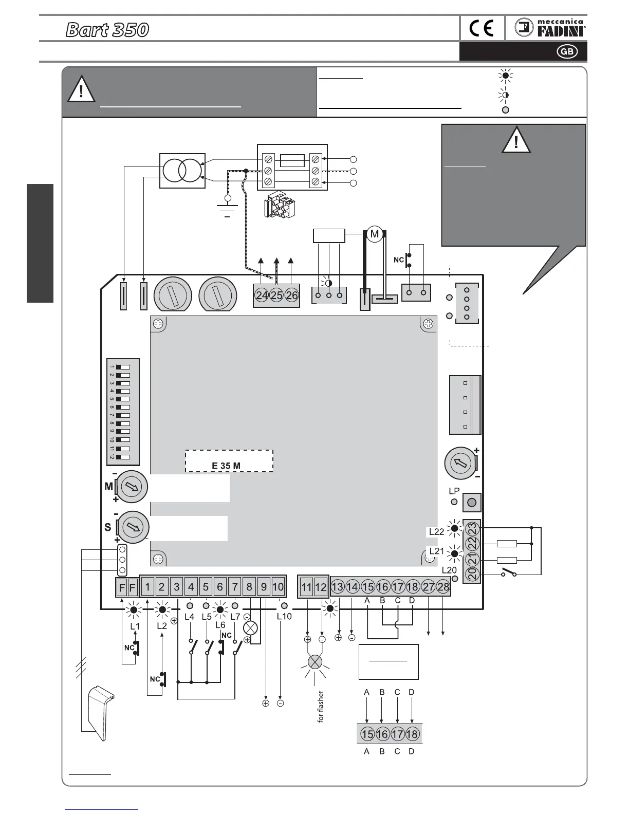
InstructionsGENERAL INFORMATION REGARDING ELPRO 35M and ELPRO 35S
English
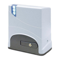
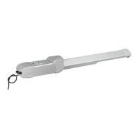
Elpro 35M
on BART 350
Master
NOTE WELL:
The LEDs shown here are in the normal state for the
proper functioning of the
ELPRO board.
The green LEDS should be always on.
LED on
LED flashing
LED off
IMPORTANT: the programmer recognises
the limit switches upon connector
insertion. Every time the connector is
inserted or removed,
YOU MUST:
1) REMOVE AND THEN RESTORE
ELECTRICAL POWER AFTER A FEW
SECONDS
2) PROGRAM BART 350
Terminals
with fuse
External power supply
230V 50Hz ± 10%.
For distances longer
than 50 m increase
wire sq. section.
Encoder
24V motor
Motor
Opening Limit
switch LED
Limit switch connector
Closing limit switch LED
Plug-on radio
connector
Trimmer
PAUSE
BART MASTER
TORQUE Trimmer
BART SLAVE
TORQUE Trimmer
Programming button
microprocessor
power
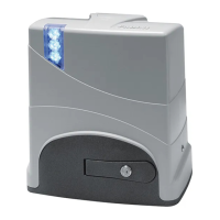
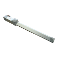
BART 350
SLAVE 3x1.5
Unlocking
handle
switch
Courtesy lamp
relay output
max 24V 50mA
Internal
receiver
photocell
External
receiver
photocell
Communication with Elpro 35S
of Bart 350 Slave on the second
gate (opening delayed), pg. 30
LED lamp
24Vdc output for max load 500mA:
2 pairs of photocells
1 Radio receiver
1 Chis 37 /Chis E37 LED or DGT61 board
5A
Transformer
F1= 6.3A
Bart 350 Master
F1= 6.3A
Bart 350 Slave
24V AC/DC output for Tx
photocell used for DSA
control
COMMON
Dip-Switch
OPEN
CLOSE
STOP
radio contact
Pilot light 24V - 1W
Output 24Vdc/DC
230V22V
OFF ON
FCAFCC
BLACK
WHITE
NOTE WELL: All of the possible connections to the programmer terminal boards are also illustrated in the respective instructions sheets for each individual
accessory.
ATTENTION: USING NON-FADINI ACCESSORIES MAY DAMAGE
THE BOARD. USE ONLY CLEAN CONTACTS WITH NO-NC INPUTS.
BRIDGE ALL UNUSED NC CONTACTS
Common
Pedestrian
8,2 kΩ or NC
8,2 kΩ or NC
safety edge in
opening
safety edge in
closing
Installation for a
single gate
bridge
A-C and B-D
LINK