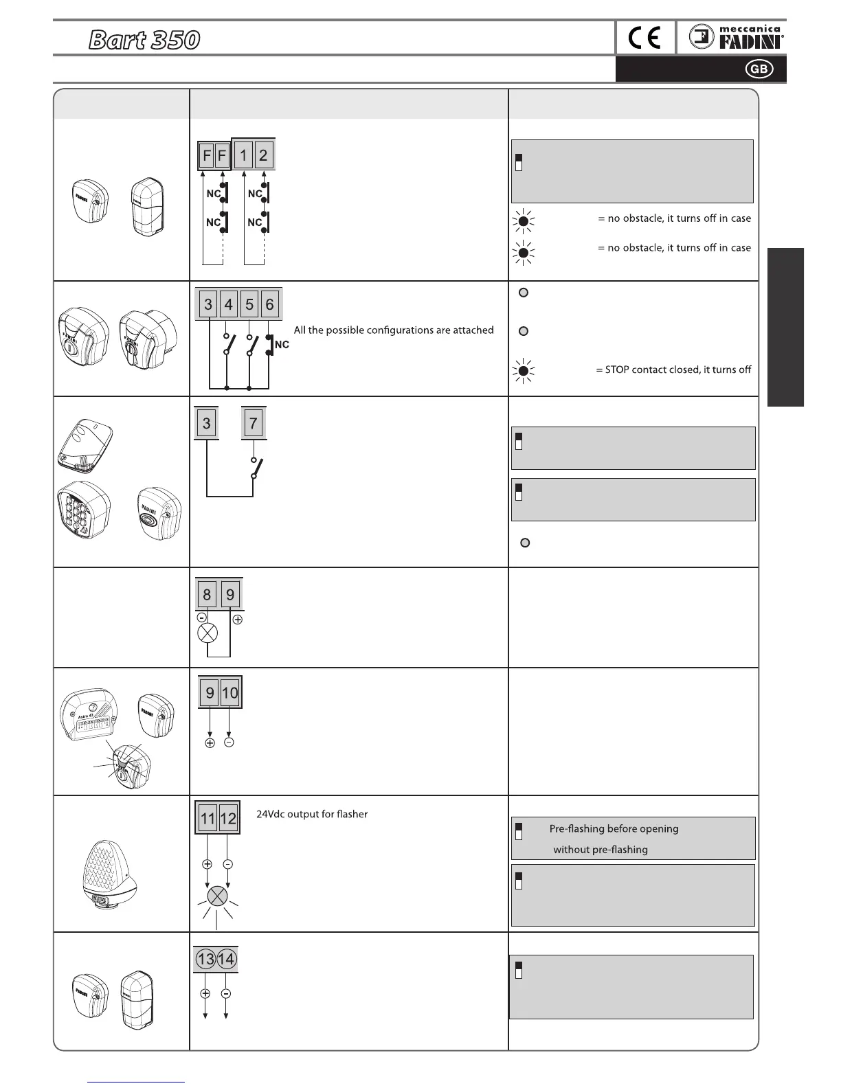
ELECTRICAL CONNECTIONS to the TERMINALS and THEIR FUNCTIONS
Seen from inside the gate:
ON: stops gate on opening and reverses it on
closing once obstacle is removed
OFF: no stop on opening, gate is reversed on
closing in case of an obstacle
ON: Does not reverse and does not stop in opening
OFF: In opening always stops and reverses
ON:
OFF:
ON: DSA control of the photocells. The photocell
projectors, outputs 13-14, must be powered
OFF: No DSA control on the photocells
L7 red O= no RADIO contact, it lights up by
any radio contact pulse
ON: Step by step with intermediate stop
OFF: Reverses direction on every RADIO pulse
ON: Flasher deactivated during Pause in
automatic operation mode (Dip 3 = ON)
OFF: Flashes during Pause in automatic mode
(Dip 3 = ON)
L1 green On
of obstacle
L2 green On
of obstacle
L4 red O = no contact OPEN, it lights up with
each opening pulse
L5 red O = no contact CLOSE, it lights up with
each closing pulse
L6 green On
by pulsing stop contact
By connecting any NO contact to the two
terminals, each pulse can perform:
- Only opening:
Dip 2=ON and Dip 5=OFF
- Reverse direction on each impulse
Dip 2=OFF and Dip 5=OFF
- Step by Step:
Open-Stop-Close-Stop
Dip 2=OFF and Dip 5=ON
Output for a possible automation status warning lamp:
Warning Lamp On= Gate Open
Warning Lamp O= Gate Closed
Flashing at 0.5s (fast)= closing movement
Flashing at 1s (normally)= opening movement
24Volt output for powering photocell projectors
(powered in parallel), for DSA control:
Device for Safety Autotest= before each movement
of the gate, if this function is enabled, all safety
accessories are checked to make sure that they are
free of obstacles, should they not, there is no start and
an error will be signalled on Bart 350 with a light that
turns to amber.
DIP-SWITCH 1:
DI
P-SWITCHES 2 and 5 (MUST NEVER be
simultaneously ON):
DIP-SWITCH 4 and 8:
DIP-SWITCH 10:
2
4
10
5
8
1
24V AC/DC Output
f
or DSA control:
24Volt dc Flasher:
24V Output:
Warning Lamp
Output
24V- 1W:
Radio Contact:
Key-switch:
Photocells:
NO and NC contacts to be connected to the
respective terminals of the key or button-
switches.
to their respective command accessories
24Vdc output for max load 500mA:
2 pairs of photocells
1 Radio receiver
1 Led key-switch Chis 37 / Chis E37 or DGT 61 board
All the instructions are attached to their respective
command accessories
Photocell projectors
Accessory Electrical connections
Dip-switches and LED indication
of their functions
DGT 61
main board
Chis 37
Fit 55
Sape 69
receiver
Chis E 37
Orbita 57
Receivers:
Astro 43
Jubi 433
Siti 63
Birio 868
External photocells:
all NC contacts of external photocell receivers
must be connected in series to terminals 1 and
2: when obstructed, the gate will re-open, if in
closing phase
Internal photocells:
all NC contacts of internal photocell receivers
must be connected in series: when obstructed,
the gate is stopped in opening, closing and
pause until cleared.
COMMON
OPEN
COMMON
CLOSE
STOP
RADIO
CONTACT
internal
external
 Loading...