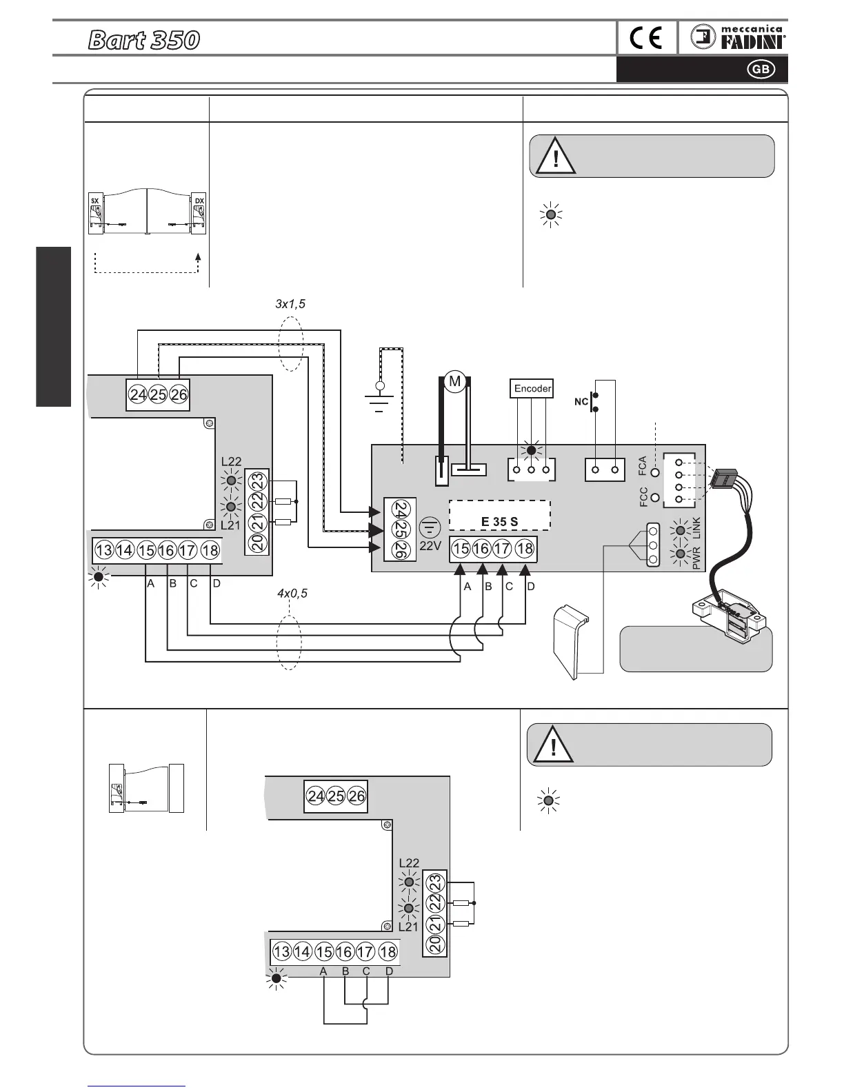
ELECTRICAL CONNECTIONS to the TERMINALS and THEIR FUNCTIONS
ATTENTION: the only electrical connections 3x1,5 and 4x0,5
between the two boards allow the Elpro 35 M programmer
to dialogue with the second Slave gate during programming
and operation.
All the accessories for command, signalling and safety must
be connected to the terminals of the Elpro 35M that manages
and controls the entire system.
Refer to the previous pages for the
Dip-Switch arrangements relative to the
individual accessories and functions
Connections for 2
Bart 350 swinging
gate operators
Connections for 1
Bart 350 swinging
gate operator
Master Slave
Accessory Electrical connections
Dip-switches and LED indication
of their functions
BLACK
WHITE
Motor 24V
Bart Slave
The GREEN LEDs, in particular the LINK LED
o
n Elpro 35M, must be on: this conrms
proper communication between the Bart
Master and Slave on respective terminals
A-B-C-D
n°3 x 1,5
n°4 x 0,5
Master
The GREEN LEDs, in particular the LINK LED
on Elpro 35M, must be on: this conrms that
terminals A-C and B-D are correctly bridged
NOTE WELL: when Bart 350 Master is to be mounted
onto a sing
le swinging gate bridge A-C and B-D.
microprocessor
Elpro 35M
on Bart 350
Master
Motor
LINK
Elpro 35M
on Bart 350
Master
LINK
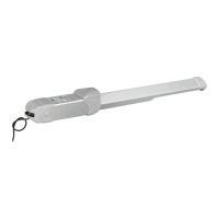
Bart Slave
release lever
switch
FCA= Bart Slave opening
limit switch LED
FCC= Bart Slave closing
limit switch LED
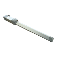
Bart Slave
limit switch
connector
Elpro 35S
on Bart 350
Slave
For installation and
adjustment of limit switch
microswitches, see pg. 11
LED lamp
Refer to the previous pages for the
D
ip-Switch arrangements relative to the
individual accessories and functions