7
1643
Drwg. No.
exp
13
GB
230V SINGLE-PHASE PROGRAMMER FOR SWING GATE OPERATORS
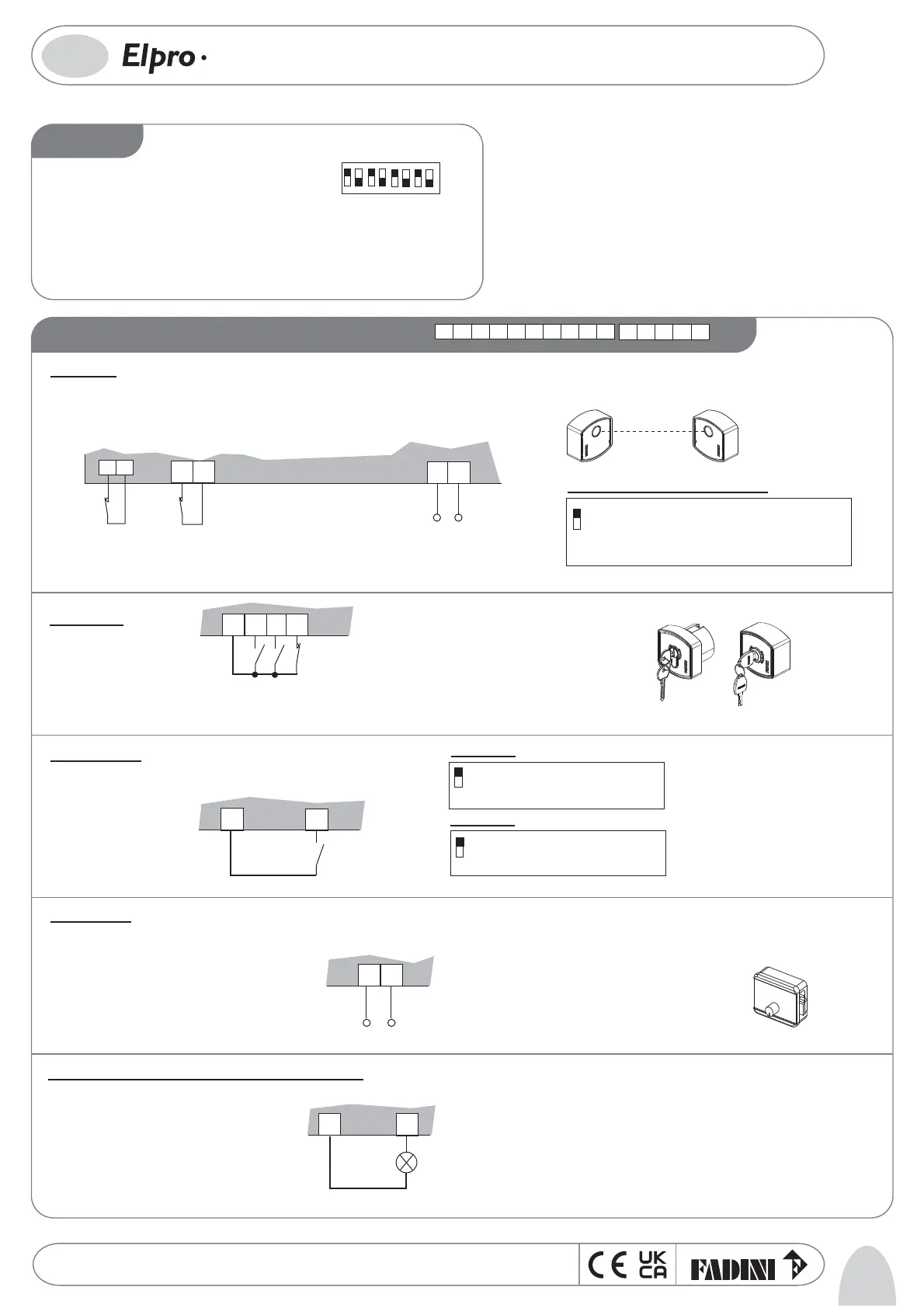
LOW VOLTAGE ELECTRICAL CONNECTIONS
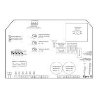
DIP-SWITCH
1= ON 1
st
pair of Photocells stop gates during opening
2= ON Radio does not invert during opening
3= ON Closes in Automatic mode
4= ON Pre-ashing of ashing light
5= ON Step-by-step by radio with intermediate stop
6= ON Single pedestrian when gate is closed
7= ON Stroke reversing pulse function enabled when opening from closed gate position
8= ON Eliminates the Leaf delay when opening. The motors start together
ON
OFF
14567823
Radio contact:
- Open/Close (normal) changes direction at each pulse
- Step-by-step with intermediate stop
Photocells:
12
13
1
2
OUTPUT 24Vac(MAX. LOAD:
2 pairs of PHOTOCELLS
1 RADIO RECEIVER)
1
DIP-SWITCH 1 (only for 1st pair of Photocells):
ON: Photocell stops gate on opening and changes direction
when closing once the obstacle has been removed
OFF: Photocell no stop on opening and changes direction
when closing in case of an obstacle
Pushbutton
switch:
2
ON: Does not change direction
during opening
OFF: Changes direction at each pulse
DIP-SWITCH 2:
ON: Step-by-step with intermediate stop
OFF: Normal operation
5
DIP-SWITCH 5:
NC CONTACT
1st pair of
PHOTOCELLS
NC CONTACT
2nd pair of
PHOTOCELLS
7
3
COMMON
RADIO
NO
10
9
24V INDICATOR LIGHT
3W max
Electric lock:
Mechanical accessory that locks the gate in closed position, recommended for installation with leaves over 1.80 m in length and non locking operators.
Operating time: power supply for 2 seconds, 100ms in advance before leaf movement starts
11
8
COMMON
24V 3W Indicator light showing leaf in movement:
Indicator light On = Gate open
Indicator light O = Gate closed
0.5s ashing (fast) = closing movement
1s ashing= opening movement
3
4
5
6
P
O
T
S
CN
COMMON
N
E
P
O O
N
D
E
S
OL
C O
N
11
12
13 14 15
1
74
10
2
85
3
96
The 1st pair of Photocells (device installed on gate posts) is managed by Dip-Switch 1
The 2nd pair of photocells (device installed inside entrance) stops during opening and changes direction when closing once the
obstacle has been removed
12V AC, 15VA OUTPUT
ELECTRIC LOCK POWER SUPPLY
Key switch:
7
 Loading...