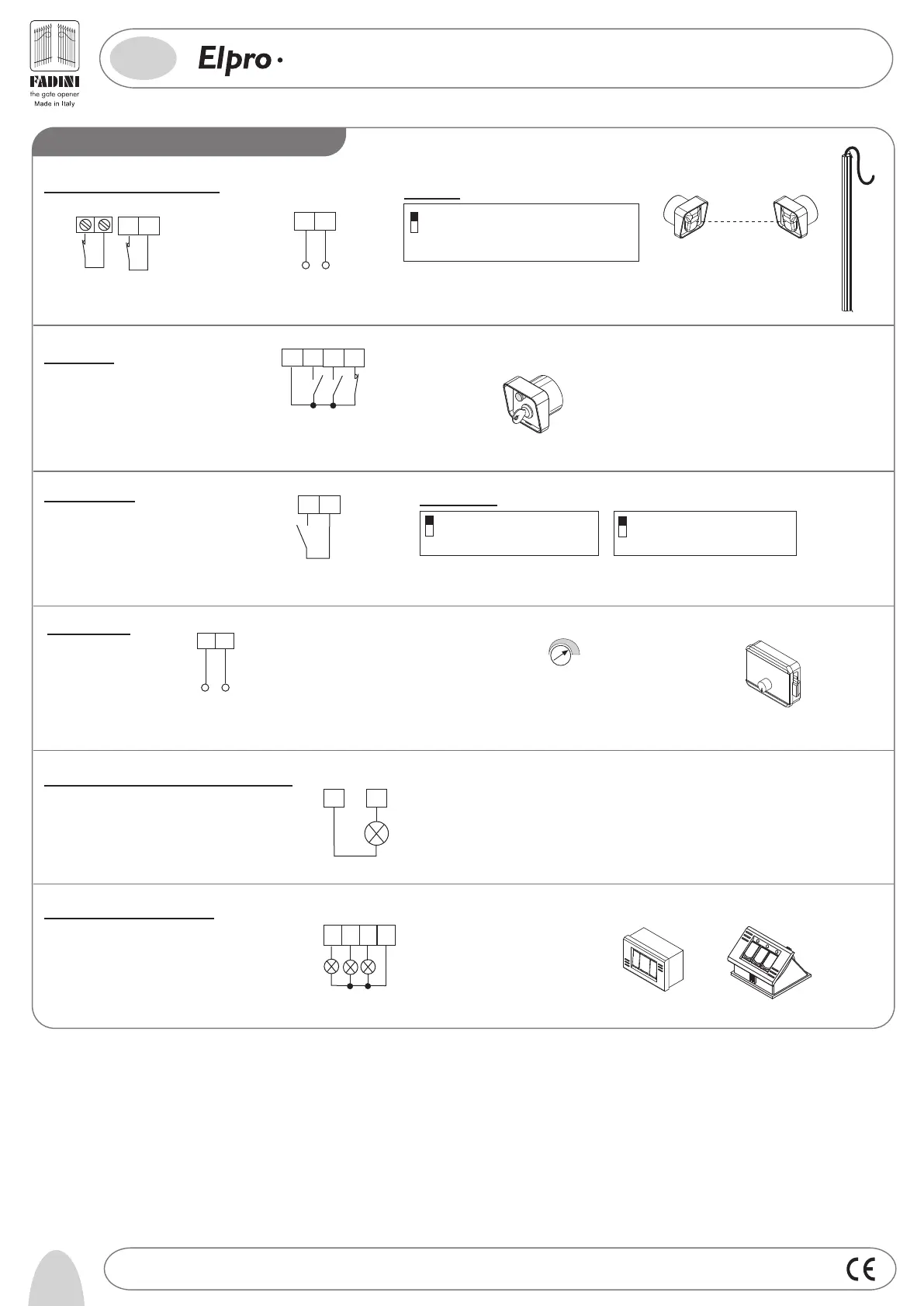
FOR SWINGING GATES
PLUS
9
Photocells and Safety Edge:
12 13
24V OUTPUT (500mm) ( MAX LOAD:
2 PAIRS PHOTOCELLS and
1 RADIO RECEIVER)
1
2
CONTACT FOR PHOTOCELLS
AND SAFETY EDGE
PHOTOCELLS 2
Keyswitch:
3
4
5
6
STOP
COMMON
OPEN
CLOSE
Radio Contact:
- Open/Close (Standard)
- Any new pulse reverses gate travel
- Step by Step
2
5
ON: Step by Step. Stop in between by
remote control
OFF: Standard Operating Mode as pre-set
ON: No gate travel reversing
on Opening
OFF:Any new pulse reverses gate travel
DIP-SWITCH 2 and 5 (NEVER set both of them to ON at the same time):
COMMON
RADIO CONTACT
8
7
Electric lock:
910
12VAC OUTPUT TO POWER
AN ELECTRIC LOCK
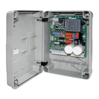
24V 3W Light for Gate Status Indication:
Light On = Gate Open
Light Off = Gate Closed
Flashing 0,5s (fast)= Gate Closing
Flashing 1s (standard)= Gate opening
Flashing 2s (slow)= Gate Stopped
8
11
1
DIP-SWITCH 1:
OFF: Photocells do not stop gates on Opening, reverse
gate travel on Closing in case of an obstacle
ON: Photocells stop gates on Opening and reverse gate
travel on Closing once obstacle has been removed
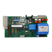
Push Button Switch Pulin3:
26
27
28
3
COMMON
These LEDs indicate when
Open - stop - Close
commands are given
-
+
T4 ABOVE MINIMUM TO
STRAIGHT CENTRE POSITION.
THE ELECTRIC LOCK IS
EXCITED FOR 4 SECONDS
By setting T4 Trimmer (Ext.Trimmer) from
above minimum position to straight
centre position, the electric lock is
excited for 4 seconds.
M1 motor is abled to take an electric
lock.
Drwg. No.
4192
6
GB
®
LOW VOLTAGE ELECTRICAL CONNECTIONS