INDEX
Section Page
Comparison table for Mill Model FAGOR 8025/8030 CNCs .........................................ix
New features and modifications ......................................................................................xv
INTRODUCTION
Safety Conditions...........................................................................................................Intr. 3
Material Returning Terms .............................................................................................Intr. 5
Fagor Documentation for the 8025/30 M CNC ..........................................................Intr. 6
Manual Contents ............................................................................................................Intr. 7
1. Overview..........................................................................................................................1
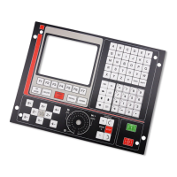
2. Front panel 8025/30 CNC...............................................................................................2
2.1. Monitor/keyboard for the 8030 CNC .............................................................................2
2.2. Control panel for the 8030 CNC.....................................................................................4
2.3. Monitor/keyboard/control panel for the 8025 CNC ......................................................5
2.4. Selection of colors...........................................................................................................7
2.5. Cancellation of monitor display .....................................................................................7
2.6. Function keys (soft keys) ................................................................................................7
3. OPERATING MODES .....................................................................................................8
3.1. 0 mode: AUTOMATIC (Continuous cycle) / 1 mode: SINGLE BLOCK .......................10
3.1.1. Execution of a program ...................................................................................................10
3.1.1.1. Selection of the Automatic (0) Single Block (1) operating modes ...............................10
3.1.1.2. Selection of the program to be executed ........................................................................10
3.1.1.3. Selection of the first block to be executed .....................................................................11
3.1.1.4. Display of the contents of the blocks .............................................................................11
3.1.1.5. Cycle Start .......................................................................................................................12
3.1.1.6. Cycle Stop .......................................................................................................................12
3.1.1.7. Changing the operating mode ........................................................................................13
3.1.2. Display modes .................................................................................................................13
3.1.2.1. Selection of the display mode ........................................................................................13
3.1.2.2. Standard display mode ....................................................................................................14
3.1.2.3. Current position display mode .......................................................................................15
3.1.2.4. Following error display mode .........................................................................................15
3.1.2.5. Arithmetic parameters display mode ..............................................................................15
3.1.2.6. Subroutine status, clock and parts counter display mode ..............................................16
3.1.2.7. Graphics display mode ....................................................................................................17
3.1.3. Programming while running a program. Background ....................................................18
3.1.4. PLC/LAN mode ...............................................................................................................18
3.1.5. Verification and modification of the values of the tool offset table
without stopping the cycle .............................................................................................19
3.1.6. Tool inspection ...............................................................................................................19
3.1.7. CNC reset ........................................................................................................................21
3.1.8. Display and deletion of the Messages sent by the FAGOR PLC 64...............................21
3.2. Mode 2: PLAY-BACK ....................................................................................................22
3.2.1 Selection of the operating mode PLAY-BACK ..............................................................22
 Loading...