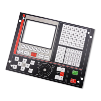
TECHNICAL DESCRIPTION
GP M MG MS
INPUTS/OUTPUTS
Feedback inputs. ........................................................................................ 6 6 6 6
Linear axes ........................................................................... 4 4 4 5
Rotary axes........................................................................... 2 2 2 2
Spindle encoder.................................................................... 1 1 1 1
Electronic handwheels ......................................................... 1 1 1 1
Probe input ............................................................................................. x x x x
Square-wave feedback signal multiplying factor, x2/x4 ........................... x x x x
Sine-wave feedback signal multiplying factor, x2/x4/10/x20 ................... x x x x
Maximum counting resolution 0.001mm/0.001°/0.0001inch.................... x x x x
Analog outputs (±10V) for axis servo drives ............................................ 4 4 4 5
Spindle analog output (±10V) ................................................................... 1 1 1 1
AXIS CONTROL
Axes involved in linear interpolations....................................................... 3 3 3 3
Axes involved in circular interpolations.................................................... 2 2 2 2
Helical interpolation .................................................................................. x x x x
Electronic threading .................................................................................. x x x
Spindle control .......................................................................................... x x x x
Software travel limits ................................................................................ x x x x
Spindle orientation .................................................................................... x x x x
Management of non-servo-controlled Open-Loop motor ......................... x
PROGRAMMING
Part Zero preset by user............................................................................. x x x x
Absolute/incremental programming .......................................................... x x x x
Programming in cartesian coordinates ...................................................... x x x x
Programming in polar coordinates ............................................................ x x x x
Programming in cylindrical coordinates (radius, angle, axis) ................... x x x x
Programming by angle and cartesian coordinate....................................... x x x x
COMPENSATION
Tool radius compensation ......................................................................... x x x
Tool length compensation ......................................................................... x x x x
Leadscrew backlash compensation............................................................ x x x x
Leadscrew error compensation.................................................................. x x x x
Cross compensation (beam sag) ................................................................ x x x x
DISPLAY
CNC text in Spanish, English, French, German and Italian ...................... x x x x
Display of execution time.......................................................................... x x x x
Piece counter ............................................................................................. x x x x
Graphic movement display and part simulation ........................................ x x
Tool base position display ......................................................................... x x x x
Tool tip position display............................................................................ x x x x
Geometric programming aide.................................................................... x x x x
COMMUNICATION WITH OTHER DEVICES
Communication vía RS232C ..................................................................... x x x x
Communication via DNC .......................................................................... x x x x
Communication via RS485 (FAGOR LAN) ............................................. x x x x
ISO program loading from peripherals...................................................... x x x x
OTHERS
Parametric programming ........................................................................... x x x x
Model digitizing ........................................................................................ x x x x
Possibility of an integrated PLC ................................................................ x x x x
Sheetmetal tracing on LASER machines................................................... x
Jig Grinder ............................................................................................. x
 Loading...