EasyManua.ls Logo

Fairchild T5200 Series - User Manual

Default Icon
10 pages
Print Icon
To Next Page IconTo Next Page
Loading...
FAIRCHILD T5200 SERIES
ELECTRO-PNEUMATIC TRANSDUCER
Installation, Operation and Maintenance Instructions
Identification Number
1
2
3
Factory Mutual Approval Only.
Intrinsically Safe Units cannot be set for Reverse Acting
Mode in field.
Units shipped calibrated 4-20 mA, 10-50 mA units must
be calibrated in field.
5200-
T
1
2
3
Underwriting Group
Approval Class
Factory Mutual
Canadian Standard
Explosion-Proof
NEMA 4X/IP65
None (leave blank)
Intrinsically Safe
None (leave blank)
Output
1-5 mA
4-20 mA
10-50mA
1-5 VDC
1-9 VDC
Input
psig
[BAR]
(KPa)
Options
Valve Mount
(F)
(C)
(XPD)
(N)
()
(I)
()
(1)
(4)
(5)
(9)
(0)
(1)
(2)
(V)
1
Figure 1. Model T5200 Series Transducer Identification Number System.
GENERAL INFORMATION
The Model T5200 Series Electro-Pneumatic Transducer converts a DC current or voltage input signal to a directly
proportional pneumatic output.
1
Question and Answer IconNeed help?

Do you have a question about the Fairchild T5200 Series and is the answer not in the manual?

Overview

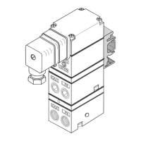
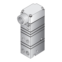
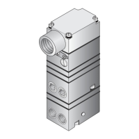
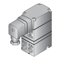
The Fairchild T5200 Series Electro-Pneumatic Transducer converts a DC current or voltage input signal to a directly proportional pneumatic output.

Functional Specifications:

  • Output Range: 3-15 psig [0.2-1.0 BAR] (20-100 kPa)
  • Supply Pressure: 20 ± 2 psig [1.5 ± 0.15 BAR] (150 ± 15 kPa)
  • Air Consumption (SCFM): 0.16 (0.27 m³/HR) Maximum
  • Output Capacity (SCFM): 0.15 (0.26 m³/HR) Maximum
  • Impedance/Input Signal:
    • 1-5 mA: 2000 Ohms (nominal)
    • 4-20 mA: 120 Ohms
    • 10-50 mA: 50 Ohms
    • 1-9 VDC: 375 Ohms
    • 1-5 VDC: 2550 Ohms

Performance Specifications:

  • Terminal Based Linearity: ±0.50% Full Scale
  • Independent Linearity: ±0.25% Full Scale
  • Hysteresis & Repeatability: within 0.1% Full Scale
  • Supply Pressure Effect: ±0.3% of span for a 1 psig [0.1 BAR] (10 kPa) supply change (18-22 psig, [1.2-1.55 BAR], (120-155 kPa))
  • Shock and Vibration Effect: Negligible up to 2 g's between 5 Hz and 200 Hz
  • Ambient Temperature: -40° F to +150° F (-40° C to +65.5° C)
  • Temperature Coefficient: Less than 1% of Span / 50° F (27.7°C)
  • Frequency Response: -3 db @ 20 Hz (unloaded)
  • RFI/EMI Effect: EMC Directive 89/336/EBC, European NORM EN 61326
  • Materials of Construction:
    • Body and Housing: Aluminum
    • Ball and Orifice: Sapphire
    • Nozzle: Stainless Steel
    • PC Board: Fiberglass

Hazardous Area Classification:

FM (Factory Mutual) Approvals:

  • Explosion-Proof:
    • (TFXPD5200): Class I, Division 1, Groups B, C, and D; Class II, Division 1, Groups E, F, and G; Maximum Ambient 65° C; NEMA 3R Enclosure. (Upright Position Only)
    • (TFXPD15200): Class I, Division 1, Groups A, B, C, and D; Class II, Division 1, Groups E, F, and G; Class III, Division 1, Fibers; Maximum Ambient 65° C.
    • (TFN5200): NEMA 4X Enclosure.
  • Intrinsically Safe:
    • (TFI5200): Class I, Division 1, Groups A, B, C, and D; Class II, Division 1, Groups E, F, and G; Class III, Division 1, Fibers; NEMA 3R Enclosure. (Upright Position Only)
    • Entity Parameters: Voc = 40 VDC, Isc = 125 mA, Ca = 0 µF, La = 0 mH. (Voc = Open Circuit Voltage, Isc = Short Circuit Current, Ca = External Capacitance, La = External Inductance)

CSA (Canadian Standards Association) Approvals:

  • Intrinsically Safe:
    • (TCI5200): Class I, Division 1, Groups A, B, C, and D; Class II, Division 1, Groups E, F, and G; Type 3 Enclosure; Rated 1-5 mA, 4-20 mA, 10-50 mA, 1-5 VDC, and 1-9 VDC; Temperature Code T4A.
    • Approvals are valid when connected through a Shunt Zener Diode Safety Barrier meeting the following parametric requirements: Rated: 28V Max. 300 Ohm Min.

Installation:

The Model T5200 can be mounted directly onto a flat surface using two 10-32 tapped mounting holes in the base of the housing (except "V" option). An optional mounting bracket (Mounting Kit EA-15268) allows for panel mounting. For pipe mounting, Optional Mounting Kit 14596 is available for a 2" pipe. The Model TXPD5200 can be mounted directly onto a flat surface using four 1/4-20x7/16 tapped mounting holes in the base of the housing (except "V" option). Mounting Kit 14140 is available for Panel or 2" Pipe Mounting.

Important Note for NEMA 3R Rating: To maintain NEMA 3R Rating for outdoor use, mount the T5200/TXPD5200 in an upright position (cover up). If not mounted in an upright position, Zero & Span Adjustments must be recalibrated for proper output range.

Pneumatic Connections:

  • Clean all pipelines before installation.
  • Apply a minimum amount of pipe compound to male threads; do not use teflon tape as a sealant. Start with the third thread back to avoid contaminating the transducer.
  • Inlet and outlet ports are labeled. Tighten connections securely. Avoid undersized fittings.
  • Instrument quality air, per ISA Standards D7.3-1981, is required. Use a filter to remove dirt and liquid in the air line ahead of the transducer. If an air line lubricator is used, it must be located downstream, beyond the transducer.
  • The user is responsible for ensuring compatibility of the environment and operating gas with transducer materials.

Electrical Connections:

  • T5200 Transducer: Make connections to the Terminal Block through a 1/2 NPT Conduit Connector (not supplied) and a plastic sleeve.
  • TXPD5200 Transducer: Make connections from the Sealed Connector Wires to an external Terminal Block. It has an additional ground wire.
  • Wiring in Hazardous Areas: Perform wiring in accordance with Table 1 (U.S.: FM, ANSI/ISARP 12.6 & ANSI/NFPA 70; Canada: CSA, CEC Part 1) and any local codes.
  • Intrinsically Safe Connections: Refer to the latest revision of the indicated drawing (FM: EC-14007; CSA: EC-16097).
  • WARNING: To prevent possible ignition of hazardous atmosphere, DO NOT REMOVE COVER from the TXPD5200 Transducer while current is on.
  • To maintain Explosion-Proof capability, DO NOT DAMAGE mating surfaces between cover and base. NEVER ADD GASKETS.
  • NOTE: The T5200 & TXPD5200 should be wired in accordance with the wiring diagram inside of cover.

Calibrations / Adjustments:

Equipment Required for Calibration:

  • Pneumatic Supply: capable of delivering up to 150 psig.
  • Current Supply: capable of delivering up to 50 mA.
  • Voltage Supply: capable of delivering up to 10 VDC.
  • Pressure Gage: capable of a digital readout up to 50 psig with an accuracy of .1%.
  • Digital Volt Meter: capable of a readout up to 30 mA or 10 VDC with an accuracy of .02%.

Adjustments Provided: Full Range Operation, Forward/Reverse Mode Calibration - Zero and Span.

Full Range Operation - Forward Acting Mode Adjustment:

  1. Connect input signal to transducer (see "Electrical Connections").
  2. NOTE: Air Supply must be connected before adjustments are made.
  3. Forward Acting Calibration-Zero: Apply minimum input signal and adjust the Zero screw for minimum output pressure (counterclockwise to increase, clockwise to decrease).
  4. Forward Acting Calibration-Span: Apply maximum input signal and adjust the Span screw on the potentiometer for maximum output pressure (clockwise to increase, counterclockwise to decrease).
  5. Repeat steps 3-4 until desired output range is obtained.

Reverse Acting Mode Adjustment:

  1. Reverse input signal connections to the transducer (see "Electrical Connections").
  2. Reverse Acting Calibration-Zero: Apply minimum input signal and adjust the Zero screw for maximum output pressure (counterclockwise to increase, clockwise to decrease).
  3. Reverse Acting Calibration-Span: Apply maximum input signal and adjust the Span screw on the potentiometer for minimum output pressure (clockwise to increase, counterclockwise to decrease).
  4. Repeat steps 2-3 until desired output range is obtained.

Maintenance:

To clean the Orifice:

  1. Shut off air supply and remove air line from Inlet Port.
  2. Remove Orifice Assembly (2) by threading a 1/4-20" Screw into the orifice housing and pulling it out through the inlet port.
  3. Clean with alcohol and dry with compressed air.
  4. NOTE: Parts must be completely dry before reassembling.

To replace PC Board:

  1. Disconnect wires from Terminal Block on PC Board (4).
  2. Unsolder Red (+) and Black (-) Leads on PC Board (4).
  3. Remove four Screws (3) holding PC Board (4) to Transducer (1).
  4. Replace PC Board (4) with the appropriate PC Board from Table 3.

To clear problems caused by Magnet malfunction:

  1. Shut off air supply. It is not necessary to remove the Transducer from air line.
  2. Remove three Screws (5) holding Magnet (6) to Transducer (1).
  3. Remove Magnet (6) and clean gap of any foreign material with masking tape.
  4. Place Magnet (6) over Coil (7) and tighten with three Screws (5).
  5. Using a non-metallic rod, raise up on the arm to make sure Coil (7) is free to move in Magnet (6).
  6. NOTES: If Coil is sticking or dragging, loosen Screws and reposition Magnet. Tighten Screws and repeat step 5.
  7. If the standard maintenance procedure does not correct the problem, install Service Kit.

Trouble-Shooting:

  • No Output: Check Supply Pressure, Clogged Orifice.
  • Leakage: Check Pneumatic Connections.
  • Low or Improper Span Adjust: Check Zero and Span Adjust, Supply Pressure Low, Output Leakage.
  • Erratic Operation: Check DC Signal, Loose Wires or Connections, Liquid in Air Supply, Dirt in Magnet Gap.
  • Unit Does Not Operate: Replace PC Board.

Fairchild T5200 Series Specifications

General IconGeneral
BrandFairchild
ModelT5200 Series
CategoryTransducer
LanguageEnglish

Related product manuals