This document is an installation and user manual for the Rapid by Fairland Inverter-Plus heat pump, designed for swimming pool heating and cooling. It provides comprehensive information for both users and professional installers, covering general information, operation, maintenance, technical specifications, and wiring diagrams.
Function Description
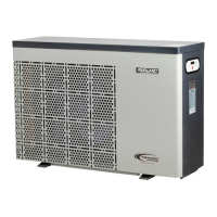
The Rapid by Fairland Inverter-Plus heat pump is an advanced system designed to efficiently heat and cool swimming pool water. It utilizes inverter technology to optimize performance and energy consumption. The unit operates in two main modes: Smart and Silence, offering flexibility based on user needs for heating capacity, speed, and noise levels. It is equipped with a power-off memory function, allowing it to restart automatically after a power recovery. The heat pump is specifically designed for pool water and should not be used for other flammable or turbid liquids.
Important Technical Specifications
The manual provides detailed technical specifications for various models (IPHCR15 to IPHCR100T), including:
Operating Conditions and Range:
- Operating Air Temperature Range: -7°C to 43°C
- Heating Temperature Setting Range: 18°C to 35°C
- Cooling Temperature Setting Range: 12°C to 30°C
- Ideal performance is achieved in an air temperature range of 15°C to 25°C.
Performance Data (at Air 26°C, Water 26°C, Humidity 80%):
- Heating Capacity (kW): Ranges from 6.5 kW (IPHCR15) to 35.8 kW (IPHCR100T).
- C.O.P (Coefficient of Performance): Ranges from 14.7~6.0 to 15.6~5.8.
- C.O.P at 50% speed: Ranges from 10.5 to 11.2.
Performance Data (at Air 15°C, Water 26°C, Humidity 70%):
- Heating Capacity (kW): Ranges from 4.8 kW (IPHCR15) to 24.5 kW (IPHCR100T).
- C.O.P: Ranges from 7.3~4.5 to 8.1~4.8.
- C.O.P at 50% speed: Ranges from 6.3 to 7.0.
Performance Data (at Air 35°C, Water 28°C, Humidity 80%):
- Cooling Capacity (kW): Ranges from 3.0 kW (IPHCR15) to 16.5 kW (IPHCR100T).
- Rated Input Power (kW) at air 15°C: Ranges from 0.13~1.06 kW to 0.61~5.2 kW.
- Rated Input Current (A) at air 15°C: Ranges from 0.56~4.60 A to 0.88~7.4 A.
- Max Input Current (A): Ranges from 6.5 A to 20.0 A.
Electrical Specifications:
- Power Supply: 230V/1 Ph/50Hz for most models; 400V/3 Ph/50Hz for IPHCR70, IPHCR70T, and IPHCR100T.
Water Flow and Noise:
- Advised Water Flux (m³/h): Ranges from 2~4 m³/h to 12~18 m³/h.
- Sound Pressure 1m dB(A): Ranges from 37.8~47.2 dB(A) to 43.5~54.9 dB(A).
- Sound Pressure 10m dB(A): Ranges from 17.8~27.2 dB(A) to 23.5~34.9 dB(A).
Physical Dimensions:
- Water Pipe In-Out Spec (mm): 50 mm for all models.
- Net Dimension LxWxH (mm): Varies by model, e.g., 894x359x648 mm (IPHCR15) to 1154x539x948 mm (IPHCR100T).
- Net Weight (kg): Ranges from 42 kg (IPHCR15) to 120 kg (IPHCR100T).
Protection Devices and Cable Specification:
- Breaker Rated Current (A): Ranges from 8.0 A to 24.0 A (for 230V models) and 9.0 A to 12.0 A (for 400V models).
- Breaker Rated Residual Action Current (mA): 30 mA for all models.
- Fuse (A): Ranges from 8.0 A to 24.0 A (for 230V models) and 9.0 A to 12.0 A (for 400V models).
- Power Cord (mm²): 3x1.5 mm² to 3x6 mm² (for 230V models) and 5x2.5 mm² (for 400V models) for cords ≤ 10m. Longer cords require increased wire diameter.
- Signal Cable (mm²): 3x0.5 mm², extendable up to 50m.
Usage Features
- Modes of Operation:
- Smart Mode: Offers 20% to 100% heating capacity with intelligent optimization for fast heating. This is the default mode upon startup.
- Silence Mode: Provides 20% to 80% heating capacity with a sound level 3dB(A) lower than Smart mode, ideal for night use.
- User Interface: The heat pump features a digital display with buttons for ON/OFF, Unlock/Mode Selection, Speed (Smart/Silence), and Up/Down for temperature adjustment.
- Screen Lock: The screen automatically locks after 30 seconds of inactivity. Pressing the unlock button for 3 seconds unlocks it.
- Temperature Setting: Adjustable temperature ranges for Auto (12~35°C), Heating (18~35°C), and Cooling (12~30°C).
- Defrosting: Includes both auto defrosting (indicated by a flashing sun icon) and compulsory defrosting, which can be initiated manually.
- Safety Reminders:
- Always ensure the water pump is on before the heat pump and off after the heat pump for extended service life.
- Do not lift the water union when moving the heat pump to prevent damage to the titanium heat exchanger.
- Keep air inlet and outlet clear of obstacles for optimal efficiency.
- Avoid using or storing combustible gases or liquids near the unit.
- In case of abnormal operation (noises, smells, smoke, leakage), immediately cut off power and contact a dealer.
- The main power switch should be out of children's reach.
- Cut off power during lightning storms.
- Error Codes: The manual lists various error codes (E1-E8, EA, P0-P9, F1-F9, FA) to help diagnose issues such as high/low pressure, water flow problems, sensor failures, and compressor/inverter board issues. It also clarifies that certain codes (E3, Ed, Eb, E6, E5) are not failures but rather indicators of normal operating conditions (no water flow, anti-freezing, out of operating range, insufficient water flow, power abnormal).
Maintenance Features
- Daily Maintenance:
- Always cut off power before maintenance.
- Clean the evaporator with household detergents or clean water; never use gasoline, thinners, or similar fuels.
- Regularly check bolts, cables, and connections.
- Winterizing:
- During the winter season when the pool is not in use, cut off the power supply and drain all water from the heat pump.
- If the heat pump is used below 2°C, ensure continuous water flow to prevent freezing and potential damage to the titanium heat exchanger.
- Professional Maintenance:
- Installation, removal, and maintenance must be performed by professional personnel.
- Gas leakage tests are required before and after installation.
- Vacuum completely before welding; field welding is not allowed and must be done by professional personnel in a maintenance center.
- If gas leakage occurs, stop installation and return the unit to a professional maintenance center.
- All operators handling gas must be qualified by valid certification.
- Strictly follow manufacturer's requirements for maintenance and gas filling.
- Annual maintenance by a qualified professional technician is recommended. Do not touch electronic components until LED indication lights on the PCB turn off.
- Troubleshooting: A table is provided for common faults, their reasons, and solutions, such as "Heat pump doesn't run" (check power, switch, fuse, breaker) or "Fan running but with insufficient heating" (check evaporator/air outlet blockage, wait for start delay, adjust set temp). Users are advised not to attempt repairs themselves.
Installation Features
- Transportation: The heat pump must be stored and moved in an upright position. Sealing is not allowed during transportation. Goods should be transported at a constant speed to avoid sudden movements. The unit must be kept away from fire sources, and storage areas should be bright, wide, open, and well-ventilated with required ventilation equipment.
- Location: Must be installed in a well-ventilated, outdoor environment, not in a closed or indoor space. Keep away from fire sources.
- Piping:
- The inlet and outlet water unions cannot bear the weight of soft pipes; hard pipes must be used.
- To ensure heating efficiency, the water pipe length between the pool and the heat pump should be ≤10m.
- Minimum distances for installation are specified: 700mm from the front, 500mm from the side, and 700mm from the back, with 2500mm from the top.
- Mounting: The frame must be fixed to a solid concrete foundation or strong, anti-rust treated brackets using M10 bolts.
- Condensation Water: The unit discharges condensation water from the bottom; a drainage tube (accessory) should be inserted and connected to a pipe for proper drainage.
- Electrical Wiring:
- Must be connected to an appropriate power supply matching the product's rated voltage.
- The heat pump must be well-earthed.
- Wiring must be done by a professional technician according to the circuit diagram.
- A breaker or fuse (leakage operating current ≤ 30mA) must be set according to local codes.
- Power and signal cables should be laid out orderly without affecting each other.
- Detailed wiring diagrams are provided for 230V/1Ph/50Hz and 400V/3Ph/50Hz power supplies, including connections for the water pump and optional heating priority functions.
- Trial After Installation:
- Before startup, all wirings must be carefully checked.
- Inspect the entire installation, pipe connections, and electrical wiring.
- Ensure the main power is well connected and no obstacles are in front of air inlet/outlet.
- It is recommended to start the water pump before the heat pump and turn off the heat pump before the water pump for longer life.
- The heat pump has a start delay function (fan starts in 3 minutes, compressor in another 30 seconds) to protect the unit.
- Check for abnormal noise and verify temperature settings after startup.