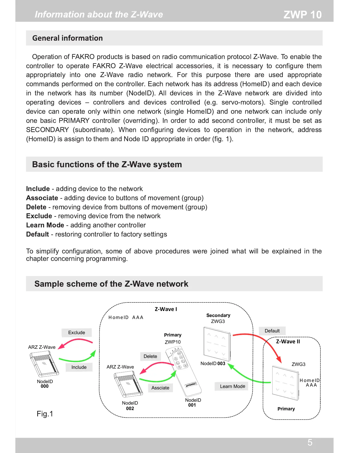
Fig.1
Information about the Z-Wave
Operation of FAKRO products is based on radio communication protocol Z-Wave. To enable the
controller to operate FAKRO Z-Wave electrical accessories, it is necessary to configure them
appropriately into one Z-Wave radio network. For this purpose there are used appropriate
commands performed on the controller. Each network has its address (HomeID) and each device
in the network has its number (NodeID). All devices in the Z-Wave network are divided into
operating devices – controllers and devices controlled (e.g. servo-motors). Single controlled
device can operate only within one network (single HomeID) and one network can include only
one basic PRIMARY controller (overriding). In order to add second controller, it must be set as
SECONDARY (subordinate). When configuring devices to operation in the network, address
(HomeID) is assign to them and Node ID appropriate in order (fig. 1 ).
Basic functions of the Z-Wave system
Sample scheme of the Z-Wave network
Include
- adding device to the network
Associate
- adding device to buttons of movement (group)
Delete
- removing device from buttons of movement (group)
Exclude
- removing device from the network
Learn Mode
- adding another controller
Default
- restoring controller to factory settings
To simplify configuration, some of above procedures were joined what will be explained in the
chapter concerning programming.