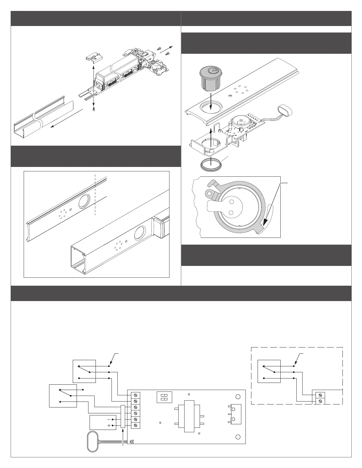
3 Remove and discard dogging assembly.
Dogging assemblies are shown below.
a
b
c
4 Cut new cover plate as needed to match exit device
length.
Cover plate
should be flush
with end of
mechanism case.
Important: Cut end of
cover plate nearest
the push bar.
ASSEMBLE AND INSTALL
5 Assemble the exit alarm unit with the parts in order as
shown below.
Ensure cylinder nut is adequately
tightened down. A loose cylinder
nut can result in inconsistent
switch actuation.
Cylinder nut
Cam should be in
OFF position before
battery is installed
or power is connected
6 If exit device does not have LM/DM or RX switch, install
switch before proceeding.
L Note: Refer to the appropriate LM/DM or RX installation
instructions.Attach wiring to terminal blocks on exit alarm
7 Attach wiring to terminal blocks on exit alarm kit board as shown.
L Notes about Wiring:
The EI (external inhibit) option uses NO (normally open) dry contacts to inhibit the exit alarm.
Closing the access control contacts inhibits the exit alarm. When the access control contacts are re-opened, the exit alarm re-arms with no
delay.
RX, LM, DM, and EI inputs are not polarized.
OR *
Gray
Black
Violet
(Optional)
Von Duprin Power Supply (PS902)
RX Switch *
Insulate unused wire
(Optional)
EI - NO
(normally open
access control
dry contacts)
NC
C
NO
24 VDC
9V Battery
Connector
EPT-10 or Electric Hinge
White
*
LM/DM Switch
Insulate unused
wire
* LM uses White/Violet
* DM uses White/Gray
GND
RX/LM/DM
GND
EXT IN
GND
24 VDC
1
2
GND
RX/LM/DM
S2
.
2
 Loading...