EasyManua.ls Logo

Falcon MEL 24 Series User Manual

Falcon MEL 24 Series
12 pages
To Next Page IconTo Next Page
Page #1 background imageLoading...
Page #1 background image
*941367-00*
941367-00
Motorized Electric Latch Retraction
MEL 24/25 Series
Installation Instructions
1 Remove end cap
These instructions are for MEL conversion kits or MEL
devices with preinstalled motors.
Parts
Do not discard
MEL 6' cable with motor cable
(47269206)
MEL motor mounting
4-20 x ¹⁄₄" FHP screws (qty 2)
Motor cable
only
(114320)
MEL motor
assembly
MEL
cover plate
Allegion Connect accessories available to order
106198 MEL-CON adapter cable with 8-pin connector
040069 MEL motor cable + MEL-CON adapter cable with 8-pin
connector
If MEL is preinstalled in the device:
If installing the MEL conversion kit, follow
the instruction steps as written.
Mark and Prepare 2 Holes
a
b
c
#25
#10-24
Wood/Madera/Bois
Metal/Metal/Métal
¹⁄₈" (3 mm) x 1" (25 mm)
Follow original device instruction up to the point
where this end mounting bracket step has been
completed.
A.
Complete MEL wiring per steps 15-21 of this
instruction.
B.
Return to original device instruction at point you left
off, and complete installation.
C.
Question and Answer IconNeed help?

Do you have a question about the Falcon MEL 24 Series and is the answer not in the manual?

Falcon MEL 24 Series Specifications

General IconGeneral
BrandFalcon
ModelMEL 24 Series
CategorySecurity System
LanguageEnglish

Summary

Product Overview and Parts

Parts Identification

Lists all components included in the MEL conversion kit or device.

Pre-installation Conditions

Instructions for MEL pre-installed devices versus conversion kits.

Initial Installation Steps

Remove End Cap

Instruction to remove the end cap from the device.

Device Disassembly and Baseplate Preparation

Remove End Mounting Bracket

Remove the end mounting bracket from the door.

Remove Old Cover Plate

Slide back, remove, and discard the old cover plate.

Remove Center Case Cover and Device

Remove the center case cover and the device from the door.

Unhook Baseplate from Center Case

Access hooking parts and unhook the baseplate.

Baseplate and Dogging Assembly Removal

Slide Baseplate Out of Mechanism Case

Slide the baseplate out of the mechanism case.

Remove Existing Dogging Assembly

Instruction to remove any existing dogging assembly.

Motor Assembly Securing

Secure Motor Assembly to Baseplate

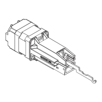
Detailed steps for securing the motor assembly onto the baseplate.

Mechanism and Case Reassembly Steps

Slide Mechanism Case onto Baseplate

Insert pushbar guide and slide the mechanism case onto the baseplate.

Reconnect Center Case and Insert Pushbar Guide

Reconnect center case to baseplate and insert remaining pushbar guide.

Reattach Mechanism Case and Device

Reattach mechanism case to center case and device to door.

MEL Wiring and Configuration

Complete Wiring Procedure

Route and connect cables, plug in connector, and reinstall bracket.

Equipment Confirmation and Option Board Installation

Confirm Equipment Compatibility

Verify MEL compatibility with power supplies and option boards.

Install Option Board(s)

Install 900-2RS, 4R, or 4RL option board(s) into power supply.

Wiring Connections and Operation Check

Connect Wires to Option Board

Connect input and output wires to the option board for typical wiring.

Check MEL Device Operation

Activate inputs and verify all MEL devices operate properly.

MEL Troubleshooting Guide

Troubleshoot Operation Using LED Indicators

Diagnose issues based on LED response and power input.

Final Installation Steps

Install MEL Cover Plate

Install the new MEL cover plate, ensuring correct end orientation.

Final Reassembly

Reinstall End Cap

Reinstall the end cap onto the device.

Reinstall Center Case Cover

Reinstall the center case cover using screws.

Warnings and Cautions Explained

Understanding Warning Symbols

Explains the meaning of Warning, Caution, Notice, and Direction symbols.

Related product manuals