Do you have a question about the Falcon 25 Series and is the answer not in the manual?
Remove and discard the existing cover plate from the exit device.
Address dogging status and remove the exit device from the door if necessary.
Remove and discard the dogging assembly from the exit device.
Cut the new cover plate to match the exit device length for proper fit.
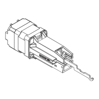
Assemble the exit alarm unit parts in the specified order.
Install LM/DM or RX switch if the exit device does not already have one.
Attach wiring to the terminal blocks on the exit alarm kit board.
Configure dip switches to set the auto-reset time for the alarm.
Partially and then fully install the new cover plate onto the exit device.
Connect the battery and slide it into its designated holder.
Reinstall the exit device onto the door after installing the alarm kit.
Reinstall the end cap bracket and then the end cap securely.
Install the required decal onto the exit device pushbar.
Insert the key and turn clockwise to position B to arm the unit.
Monitor the LED and listen for the horn to confirm arming and operational status.
Turn the key counterclockwise to position C to disarm the unit.
Follow steps to remove the end cap, slide out the assembly, and replace the battery.
This document describes the Falcon 24/25 Series Exit Alarm (EA) Kit, providing installation and operating instructions.
The Falcon 24/25 Series Exit Alarm (EA) Kit is designed to add an alarm function to an existing exit device. When armed, the alarm will sound if the exit device pushbar is pressed, indicating an unauthorized exit. The kit requires an RX (Request to Exit) or LM/DM (Latch Monitor/Door Monitor) switch to be mounted in the exit device for proper operation. It is compatible with mortise cylinders with a straight cam (1-1/4" or 32 mm) which are sold separately. The alarm can be armed and disarmed using a key.
| Microwave Frequency | 10.525 GHz |
|---|---|
| Detection Method | Microwave + PIR |
| Coverage Angle | 90 degrees |
| Current Consumption | 25 mA |
| Tamper Output | NC, 28VDC, 0.15A |
| Power Input | 12V DC |
| Input Voltage | 12V DC |