Do you have a question about the Falcon 24 Series and is the answer not in the manual?
Steps to prepare the exit device before installing the alarm kit.
Critical requirement for a specific switch type in the exit device.
Instructions for removing the dogging assembly from the exit device.
How to cut and fit the new cover plate to the exit device.
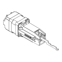
Steps for assembling the exit alarm unit and ensuring cylinder nut is tight.
Install LM/DM or RX switch if the exit device does not have one.
Detailed diagram for connecting wires to the exit alarm kit board.
Adjusting dip switches for automatic alarm reset time.
Partially install cover plate and connect the battery correctly.
Reinstalling end cap bracket, end cap, and applying the decal.
How to arm the exit alarm unit using the key.
Understanding LED indicators for armed mode.
How to disarm the exit alarm unit.
Procedure for changing the battery, including low battery warnings.
This document describes the Falcon 24/25 Series Exit Alarm (EA) Kit, providing installation and operating instructions.
The Falcon 24/25 Series Exit Alarm (EA) Kit is designed to add an alarm function to an existing exit device. When armed, the alarm will sound if the exit device pushbar is pressed, indicating an unauthorized exit. The kit requires an RX (Request to Exit) or LM/DM (Latch Monitor/Door Monitor) switch to be mounted in the exit device for proper operation. It is compatible with mortise cylinders with a straight cam (1-1/4" or 32 mm) which are sold separately. The alarm can be armed and disarmed using a key.
| Brand | Falcon |
|---|---|
| Model | 24 Series |
| Category | Security System |
| Language | English |