Sa. Nr. 213 724 0
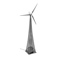
WINDKRAFTANLAGE »NORDEX«
»NORDEX« WIND GENERATOR
INSTALLATION D’ÉNERGIE ÉOLIENNE »NORDEX«
WINDKRACHTINSTALLATIE »NORDEX«
Art. Nr. 130381
Vor Beginn des Bastelns sollten Sie sich mit den Spritzlingen und der Anleitung vertraut machen.
Sollte es einmal vorkommen, dass ein Teil im Bausatz fehlt, kreuzen Sie bitte das fehlende Teil in
der Anleitung an und schicken Sie diese bitte an Fa. Gebr. FALLER GmbH, Abt. Kundendienst,
kundendienst@faller.de, Kreuzstraße 9, 78148 Gütenbach. Sie erhalten dann umgehend Ersatz.
In diesem Bausatz sind einige Kunststoffteile übrig.
Before beginning with the assembly please familiarize yourself with the parts and read the instructions carefully.
In case of missing parts please indicate these on the instructions leaflet with a circle and return
the leaflet to Gebr. FALLER GmbH, kundendienst@faller.de, Kreuzstraße 9, D-78148 Gütenbach, Germany.
You will receive the replacement by return.
Some of the parts in this box are not needed to construct the model.
Avant de commencer le montage de votre maquette bien lire la notice et repérer les grappes.
Si une pièce manque dans une boîte, cochez la pièce correspondante sur la notice et renvoyez-la-nous à
Gebr. FALLER GmbH, kundendienst@faller.de, Kreuzstraße 9, D-78148 Gütenbach (R.F.A.).
Nous vous ferons parvenir la pièce par retour.
Dans cette boîte se trouvent quelques pièces qui ne seront pas utilisées pour le montage.
Vóór het bouwen zou men de gietstukken en de handleiding moeten bestuderen.
Indien onverhoopt een onderdeel aan het bouwpakket ontbreekt, gelieve men het ontbrekende deel
in de handleiding aan te kruisen en deze te zenden aan Gebr. FALLER GmbH, kundendienst@faller.de,
Kreuzstraße 9, D-78148 Gütenbach. U ontvangt dan omgaand en gratis het ontbrekende onderdeel.
Van dit bouwpakket worden enkele kunststof delen niet gebruikt.
D
F
GB
NL
Art. Nr. 170688
SPEZIAL-SEITENSCHNEIDER
zum gratfreien Abtrennen von feinsten
Spritzteilen.
Nur für Polystyrol geeignet.
Special side cutter for cutting off ultra-fine moul-
ded parts without burrs.
Only suitable for polystyrene.
Pince coupante spéciale pour couper sans bavure
les pièces miniatures moulées par
injection. Convient uniquement au polystyrène.
Speciale zijkniptang voor het braamloos afknip-
pen van de fijnste gietstukdelen.
Alleen geschikt voor polystyrol.
Für den Zusammenbau des Modells empfehlen wir folgende FALLER-Artikel (sind nicht im Bausatz enthalten):
For the assembly of the kit we recommend following FALLER products (not included in the kit):
Pour l’assemblage du modèle, nous vous recommandons les articles FALLER suivants (non inclus dans le kit):
Om dit model te bouwen adviseren wij de volgende FALLER producten (maken geen deel uit van deze bouwset):
Art. Nr. 170492
FALLER-EXPERT
Flüssigkleber in Plastikflasche mit Spezialkanüle
für feinste Klebstoffdosierung.
Liquid cement in plastic bottle with canule
for very fine dosage.
Colle liquide en bouteille plastique
avec bec verseur pour un dosage précis.
Vloeibare lijm in plastic-flacon met doseerbuisje om
nauwkeurig te lijmen.
Wichtig: Entscheiden Sie sich vor dem Zusammenbau für eine der 3 Varianten.
Important: Before assembly decide on one of the 3 variations.
Important: Se décider avant le montage pour l’une des trois variantes.
Belangijk: Kies vóór het bouwen één van de 3 varianten.
Variante I Variante II
Inhalt Spritzlinge
Contents Sprues
Contenu Moulages
Inhoud Gietstukken
1
2
x
2
1
x