Do you have a question about the Fanimation BTCR9 and is the answer not in the manual?
Connect wires as per Figure 1 and install the receiver into the hanger bracket, taking care not to pinch wires.
Match receiver and transmitter by setting dip switches and initiating pairing via the fan off button.
Details on using remote buttons for light control, fan speed, dimming, and smart device app usage.
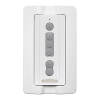
Instructions for attaching the wall plate to the wall using the two provided screws.
This document provides instructions for wiring and operating the BTCR9 Remote Control for ceiling fans. It covers the installation of the receiver, pairing the transmitter, and the functions of the transmitter and wall plate.
The BTCR9 Remote Control system is designed to provide wireless control over ceiling fan functions, including fan speed and light operation. It consists of a receiver unit that is installed within the fan's canopy and a handheld transmitter, along with an optional wall plate for convenient access. The system is designed for ease of use and offers features for both basic and advanced control, including smart device integration.
Receiver Unit: The receiver unit acts as the intermediary between the transmitter and the ceiling fan. It receives signals from the transmitter and translates them into commands for the fan's motor and light kit. The receiver is designed to be compact, fitting within the fan's hanger bracket and covered by the canopy. It features a dimmer switch to select between dimmer functionality for incandescent bulbs and on/off functionality for CFL bulbs, ensuring compatibility with different lighting types. The receiver can be paired with up to five transmitters, offering flexibility for multi-user or multi-location control. Smart device pairing is unlimited, allowing for extensive control options through the fanSync app.
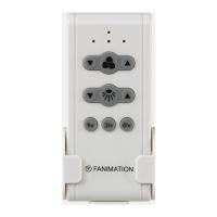
Transmitter Unit: The handheld transmitter provides the user interface for controlling the ceiling fan. It features several buttons for various functions:
The transmitter operates using a CR2430 3V battery, which is accessible under a cover. It also includes dip switches for setting a unique code, which is essential for pairing with the receiver and preventing interference with other remote-controlled fans.
Wall Plate: The wall plate provides a fixed location for the transmitter, offering an alternative to the handheld operation. It is designed to be easily attached to a wall using provided screws, ensuring the transmitter is always accessible and neatly stored.
Installation and Wiring: The installation process begins with ensuring the main electricity is turned off at the fuse box for safety. The ceiling fan must be set to HIGH speed, and any light kit must be in the ON position before wiring. The receiver wires are connected to the fan and supply wires according to a specific diagram, matching colors (e.g., black to black, blue to light/live, white to white). Once wired, the receiver slides into the hanger bracket, and the canopy covers it, concealing the unit.
Pairing Process: The receiver and transmitter are factory-matched, but if either unit is replaced, a re-pairing process is required. This involves setting the desired transmitter code using the dip switches (located under the battery cover). After setting the code, power is restored to the fan, and the fan off button on the transmitter must be pressed and held for 1 to 3 seconds within 30 seconds of restoring power. A successful pairing is indicated by the light blinking twice and the fan turning on to medium speed. This process allows multiple transmitters to control a single receiver, or a single transmitter to control multiple receivers, provided care is taken to avoid unintended pairings, especially for fans less than seven feet apart.
Lighting Control: The system offers flexible lighting control. For incandescent bulbs, the "light dimmer function select switch" on the receiver should be set to the dimmer position, enabling variable light intensity. For CFL bulbs, the switch should be set to the on/off position, providing simple on/off functionality without dimming.
Smart Device Integration: A significant feature of this system is its compatibility with smart devices. Users can download the fanSync app to control their receiver via their smartphone or tablet. This extends the control capabilities beyond the physical transmitter, offering a modern and convenient way to manage fan and light functions.
Battery Replacement: The transmitter operates on a CR2430 3V battery. While the manual does not explicitly detail the battery replacement process, it implies that replacing the battery does not necessitate re-pairing the device, simplifying maintenance. The battery is accessible under a cover on the transmitter.
Troubleshooting (Implicit): The manual's emphasis on correct wiring and the pairing process serves as a guide for troubleshooting common issues. For instance, if the fan or light does not respond, checking the wiring connections, ensuring the fan is set to high speed and the light is on, and re-performing the pairing process are implied first steps. The warning about incorrect wiring damaging the receiver also highlights the importance of careful installation to prevent future maintenance issues.
Professional Assistance: The document advises seeking assistance from a qualified electrician if the fan or supply wires are different colors than indicated, or if the outlet box is not grounded. This ensures safe and correct installation, preventing potential electrical hazards and ensuring the longevity of the device.
In summary, the BTCR9 Remote Control system offers comprehensive and user-friendly control over ceiling fans and their integrated lighting. Its design focuses on ease of installation, flexible control options, and compatibility with various lighting types, all while incorporating modern smart device integration.
| Battery Quantity | 1 |
|---|---|
| Compatibility | Fanimation Fans |
| Control Functions | Fan speed, light on/off/dim, reverse |
| Battery Type | CR2032 |
| Mounting | Wall mount bracket included |