Do you have a question about the FANOX SIA-C and is the answer not in the manual?
Procedures for safely unpacking and inspecting the relay upon receipt.
Guidelines for inspecting relays upon delivery to check for transport damage.
Precautions for handling sensitive electronic components to prevent electrostatic discharge damage.
Requirements for qualified personnel, protection measures, and essential checks before powering the device.
Recommendations for storing relays in a dust- and humidity-free environment.
Guidelines for safe disposal of the device and its components.
Detailed dimensions for SIA-C relays with B and C type mechanics, including cut-out patterns.
Visual representation of the required panel cut-out dimensions for mounting.
Detailed dimensions for SIA-C relays with D type mechanics, including cut-out patterns.
Detailed dimensions for SIA-C relays with E and G type mechanics, including cut-out patterns.
Detailed dimensions for SIA-C relays with F type mechanics (withdrawable), including cut-out patterns.
Physical dimensions of the KITCOM adapter accessory.
Mechanical dimensions for striker components.
Technical specifications and dimensions for the PRT-15 striker mechanism.
Dimensional data for the PRT striker type, presented in a table.
Physical dimensions of the TCM adapter accessory.
Wiring diagrams illustrating various connection configurations for SIA-C relays.
Connection diagram illustrating power and measurement wiring for various SIA-C configurations.
Connection diagram for simple terminals, illustrating power and measurement wiring for SIA-C.
Connection diagram for Mechanic G, showing power and measurement with solid neutral configuration.
Connection diagram for Mechanic F, showing power and measurement with solid neutral configuration.
Illustration of the terminal layout for SIA-C devices with type D mechanics.
Illustration of the terminal layout for SIA-C devices with types B and C mechanics.
Illustration of the terminal layout for SIA-C devices with type E mechanics.
Illustration of the terminal layout for SIA-C devices with type F (withdrawable) mechanics.
Illustration of the terminal layout for SIA-C devices with type G mechanics.
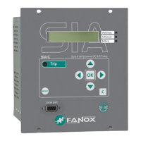
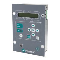
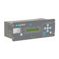
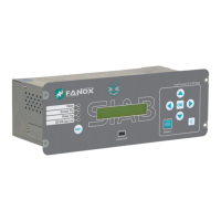
Overview of the SIA family of products designed for secondary distribution protection.
Detailed explanation of the SIA-C device's features, including self-powering and protection functions.
Description of different SIA-C mechanics (B, C, D, E, F, G) and their features.
A schematic illustrating the functional blocks and interconnections within the SIA-C relay.
Guide for selecting and ordering SIA-C relays based on protection functions, adaptation, and options.
Guidance on selecting appropriate current transformers (CTs) for SIA-C relay models.
Graphical representation of the load curve for SIA-C/1 relay.
Graphical representation of the load curve for SIA-C/5 relay.
Configuration parameters for general settings like identification, frequency, and CT ratios.
Detailed settings for the phase instantaneous overcurrent protection function (50-1/50-2).
Settings for the phase inverse time overcurrent protection function, including curve types and time delays.
Settings for the neutral instantaneous overcurrent protection function (50G-1/50G-2).
Settings for the neutral inverse time overcurrent protection function.
Settings for the negative sequence inverse time overcurrent and phase balance relay function.
Function for detecting phase unbalance due to open phase conditions based on I2/I1 percentage.
Function monitoring machine heating and cooling based on thermal image calculations.
Graphical display showing thermal image evolution based on applied current and thermal constants.
Visual representation of thermal protection curves for different conditions.
Function to monitor circuit breaker status and perform preventive maintenance using various parameters.
How to execute circuit breaker opening and closing commands via HMI or remote communication.
Counter for tracking the number of circuit breaker openings and associated alarms.
Counter for accumulating amperes during breaker openings, used for aging estimation.
Alarm triggered when the number of openings exceeds a configured limit within a time window.
Function to monitor breaker failure after a trip command, based on current measurement.
Functionality for automatic reclosing attempts after a fault, with configurable parameters like number of attempts and times.
Dedicated counter for recording the number of reclosing operations.
Function to manage load pickup conditions after a power restoration, with configurable time parameters.
Function to supervise current transformers and detect phase loss based on current thresholds.
Function to block undesirable trips caused by inrush current using second harmonic analysis.
Functionality for an external trip input, typically connected to a thermal sensor on a power transformer.
Function for implementing zone selection interlocking using configurable inputs and outputs.
Monitors trip voltage to ensure sufficient energy for the opening mechanism.
Allows configuration of multiple sets of protection parameters for different operating scenarios.
Description of inverse time overcurrent curves compliant with IEC 60255-151 standard.
Description of inverse time overcurrent curves compliant with IEEE standards.
Practical examples illustrating the use of overcurrent protection functions and their coordination.
Details on measured parameters like phase currents, neutral current, and harmonic analysis.
Function for recording and analyzing current demand over time, with characteristics and record format.
Counters for tracking circuit breaker openings, accumulated amperes, and reclosings (adaptation C only).
Information on device states, associated events, and how they are registered and stored.
Capability to store fault reports and events, including COMTRADE format export for detailed analysis.
Diagnostic algorithms that run to ensure the device's operational condition, identifying errors and anomalies.
Functionality for maintaining and synchronizing the device's date and time.
Configuration and function of the device's digital inputs, including logical states and minimum current requirements.
Details on configurable digital outputs, their default configurations, and activation current requirements.
Explanation of PGC concepts, physical inputs/outputs, logical signals, and configurable LEDs.
Available commands for device operation like opening/closing breakers, recloser control, and reset functions.
Menu for testing the operation of signalling components, trip output, and signalling outputs.
Overview of power supply options including self-powering, battery, and auxiliary power sources.
Details on powering the device using a 12V battery via the KITCOM adapter.
Information on using 230 Vac auxiliary power from the transformation centre.
Details on using 24 Vdc or 48 Vdc auxiliary power from the RTU supply.
Option for an internal commissioning battery for device setup and fault analysis.
Characteristic defining the device's starting up time and fast tripping capability during energization.
Tripping time curves for SIA-C models with striker, under self-power conditions.
Tripping behavior for SIA-C withdrawable models, detailing self-power operation.
Tripping time curves for SIA-C models with coil activation, under self-power conditions.
Explanation of different trip types (polarized, simple) and their activation mechanisms.
Details on striker activation, including its characteristics and electrical requirements.
How coil activation is achieved using a free potential contact.
Method for coil activation using the TCM adapter for opening mechanisms.
Detailed technical specifications for various protection functions, including enable, tap, time delay, and accuracy.
Specifies the thermal resistance limits of the relay and its terminals under different current conditions.
Lists the standards and test measurements applied to the SIA-C relay.
Overview of communication capabilities via RS232 and optional RS485 ports for local and remote connectivity.
Details on the front RS232 port, connector type, and communication protocols used.
Information on the optional rear RS485 port for SCADA integration, including protocol and connection requirements.
Explanation of the bistable magnetic indicators that show trip causes, even without power.
Description of the configurable LED indicators on the front panel and their default meanings.
Details on the alphanumeric LCD screen and the 6-key membrane keypad for navigation and parameter adjustment.
Information about the SICom software for device configuration, monitoring, and event management.
Step-by-step instructions for installing the SICom software package.
Explanation of user authentication through passwords and access levels for device configuration.
Overview of the different menu options available on the SIA-C relay.
Description of the default screen displaying device model and current measurements.
Guide on navigating through the device menus using the front panel keys.
Procedure for accessing and modifying the device's date and time settings.
How to access and display the software versions of the relay processors.
How to view the local and remote communication parameters of the device.
How to adjust the LCD contrast level using the keypad.
Instructions for accessing and using the test menu to verify component operations.
Overview of the main sections within the SIA-C relay's menu system.
How to access and view measurements for phase, neutral, and sequence currents.
Guide to navigating the status menu and checking the active states of various device functions.
Guide on accessing and modifying device settings, including passwords and general parameters.
How to access, view, and delete events recorded by the device.
Accessing and managing counters for openings, accumulated amperes, and reclosings (adaptation C).
Lists available commands for controlling the relay, such as breaker operations and recloser functions.
Accessing and viewing current demand registers, including date-time and phase/neutral currents.
How to access and manage fault reports, including deletion procedures.
Guide for assigning instantaneous states to physical outputs using logical gates.
Reference to commissioning sheets found in the appendix for recording the process.
General advice to pay attention to specific aspects during installation.
Reminder to consult the manual section on electrostatic discharges before handling components.
Check that cabling is installed according to external connection diagrams.
Importance of correct earthing connection for the device.
Warning about high voltage in secondary circuits of current transformers.
Requirement to specify auxiliary power needs when ordering the relay.
Test procedure for the RS232 port using SICom software to check communication errors.
Safety measures and recommendations before initial startup or after a trip event, including using KitCom and complete test menu.
Fields for recording identification details of the installed device.
Checkpoints for cabling, earth, and Vaux value.
Check list for testing LEDs, outputs, and bistable indicators.
Section for recording commissioning parameters like password, identification, CT ratios, and function settings.
Checklist for external trip and digital inputs.
Checklist for trip output and digital outputs.
Checklist for LED indicators.
Space for recording comments, person in charge, and maintenance performed.
| Frequency | 50/60 Hz |
|---|---|
| Digital Outputs | 4 |
| Storage Temperature | -40°C to +85°C |
| Humidity | Up to 95% non-condensing |
| Mounting | DIN Rail |
| Communication | Modbus RTU |
| Protection Functions | Overcurrent, Overvoltage, Undervoltage |
| Dimensions | 90 x 70 x 60 mm |
| Weight | 0.3 kg |
| Standards | IEC 60255, IEC 61000 |