07
Ed. 1 - 03/2019Ed. 1 - 03/2019
ENGLISH
EN_36
Cleaning and Maintenance
If the quick release lever has not
been closed properly, the wheel
may shift or come loose. This may
result in hazardous riding condi-
tions, falls and accidents.
5.d - Removing the rear wheel
- Using the gear change lever, transfer the chain
to the smallest sprocket (see paragraph “2” -
Section “05”) (g. “75“).
- Position the bicycle so that it is stable and
the rear wheel is o the ground.
- Push the gear change unit forward and press
the button (t) to lock it in place (g. “76“).
The tension on the chain is released.
- Using a 6 mm wrench, unscrew the axle pin
from the brake side (g. “77“).
- Slide the axle pin out of the frame.
- Disengage the chain from the sprocket and re-
move the wheel (g. “78“).
- Insert the transport block (f - supplied) be-
tween the brake pistons (g. “69“).
Never operate the hydraulic brakes when the
wheel unit has been removed. Use the trans-
port blocks (f - supplied) and remember to re-
move them before replacing the front wheel
(g. “69“).
5.e - Mounting the rear wheel
- Remove the transport block (f) from the brake
pistons (g. “79“).
Do not operate the rear brake lever.
- Insert the wheel between the frame forks, posi-
tioning the chain on the smallest sprocket and
making sure that the brake disk is positioned
between the brake piston (g. “80“).
- Insert the axle pin from the brake side and
push it until it protrudes from the other end of
the wheel hub (g. “81“).
- Using a 6 mm wrench, tighten the axle pin
from the brake side (g. “82“).
- Apply the correct tightening torque to
the axle pin (see the chart at the end
of section “3”).
- Push the gear change unit forward to release it
(g. “83“).
- Make sure that the wheel turns freely.
6. FLAT TYRE
- In the event of a at tyre, rst of all, attempt to
re-inate it, if the tyre deates again it may be
punctured or damaged.
- If you need replace a tyre we recommend you
contact your vendor or a bicycle tyre tter.
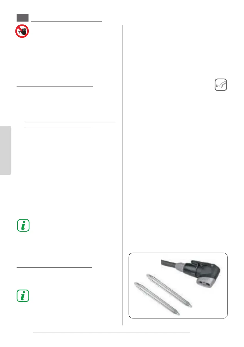
- If you wish to repair a tyre yourself, make sure
you have the following items:
- 2 tyre levers
- A (new) inner tube having the same type of
valve and dimensions as the one to be re-
placed
- A new tyre (if necessary)
- A compatible bicycle pump
If repairs are not carried out cor-
rectly it may result in dangerous
riding conditions. Do not attempt
to carry out this repair if you do
not have the necessary tools.
- Remove the wheel unit (see the preceding par-
agraphs in the section).
- Remove the valve safety cap (2) (g. “17“).
- Deate the tyre completely by pressing the in-
ner valve “3” (g. “18“).
- Lift the tyre away from the wheel rim using the
tyre levers and starting from the point oppo-
site the valve.
- Remove the inner tube from inside the tyre.
Make a note of how the inner tube was aligned
inside the tyre.
- Identify the cause of the puncture:
· Inate the defective inner tube using the bi-
cycle pump.
· Attempt to nd the point where the air es-
capes.
· If it is possible to identify the air leak, twist
the inner tube around so that the valve is
pointing inwards.
- If the leak is located on the inner surface:
· Check that the rim protection band is posi-
tioned correctly in its housing.
· Check that all the spoke holes are covered. If
not, contact your vendor.
 Loading...