III- 12
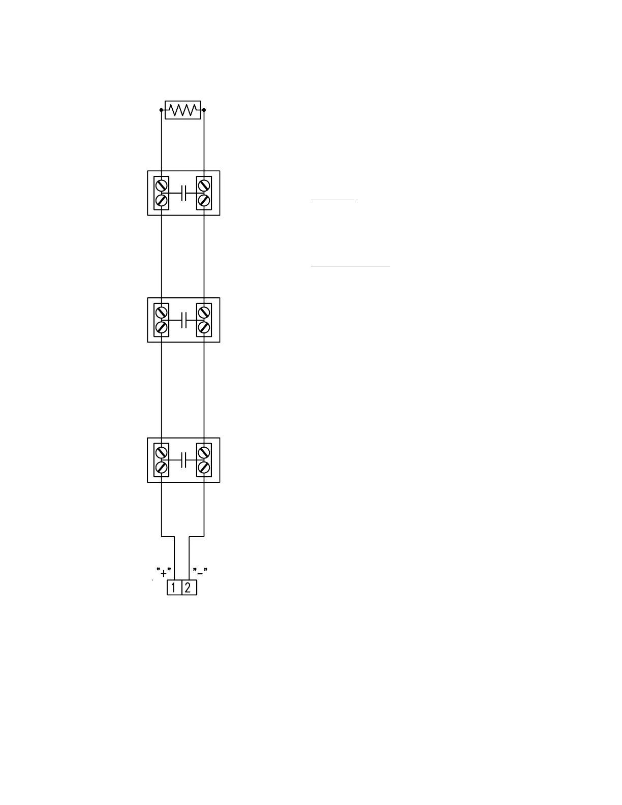
TYPICAL INITIATING DEVICE WIRING DIAGRAM
SUPERVISORY SWITCHES
Notes:
1.) This wiring diagram only shows general
information about the initiating device. For
specific wiring and installation information
read the instructions provided with each
device.
2.) For initiating circuit specifications see the
15220A Wiring Diagram (445928) or the
15240A Wiring Diagram (445929).
END OF LINE RESISTOR
(3.9K OHM 1/2 WATT)
WATERFLOW SWITCH
FARADAY CAT. NO.
PM6615, PM6616, PM6617, PM6618,
PM6619, PM6620, PM6621, PM6622,
PM6679, PM6780
SYSTEM SENSOR CAT. NO.
WFD20, WFD25, WFD30, WFD30,
WFD40, WFD50, WFD60, WFD80,
EPS10-1, EPS10-2
WATERFLOW SWITCH
WATERFLOW SWITCH
Note: When Waterflow Switches are used, they should
be connected to Zone #2 as shown. If Signals are
required to be Silenceable, Resistor R85 must be
cut out out on the Main Board.
INITIATING
CIRCUIT #2