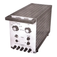
The Farnell B30 range of sub-bench power supplies combines the flexibility of bench power supplies with the simple mechanical concept of modular sub-units, resulting in economical, utility power supplies suitable for a wide variety of applications. These units can be used on or under a laboratory bench, or built into test benches or other equipment where a convenient adjustable source of DC power is needed without constant metering. The range includes four models: B30/2, B30/5, B30/10, and B30/20.
Function Description:
The B30 series consists of four single-output, variable DC power supplies in sub-unit form, utilizing silicon semiconductors throughout. The output voltage of each unit is varied by a coarse switched control and a fine control, allowing continuous variation over each switched range. Overload protection is provided by current limiting circuitry, which reduces the output current on short circuit on all ranges except the lowest, where the output current remains roughly constant on overload. The output voltage automatically resets when the overload is removed. Cooling is achieved by air convection, requiring free airflow into the bottom and out of the top of the unit.
The instruments operate from 50/400 Hz mains supplies, with selectable voltages of 105, 110, 115V or 210, 220, 230, 240V via a simple tap change on the transformer primary. Mains input is supplied via a permanently attached cable, and the DC output is drawn from terminals on the front panel. Feedback terminals are provided for remote sensing of the voltage at the load, minimizing the effects of resistance in the load connecting leads. Electronic current limiting circuitry and input/output fuses protect the unit against overload or accidental short circuits. The limiting circuitry automatically resets itself when the overload is cleared. A cable wrap underneath the unit is provided for stowing the mains lead.
Important Technical Specifications:
Mains Input:
- Standard: 240V, 50/400Hz.
- By internal link changes: 210, 220, 230V, 50/400Hz; 105, 110, 115V, 50/400Hz.
- Mains Variation Tolerated: 10%.
Output Voltages and Current Ranges:
- Output Voltage (all models): 0-30V, fully variable by a 5-position switch (6V steps) and fine control.
- Output Current:
- B30/2: 2A
- B30/5: 5A
- B30/10: 10A
- B30/20: 20A
Regulation:
- Line Regulation (for 10% mains change):
- Less than 0.01% (1mV short term)
- Less than 0.02% (2mV long term)
- Load Regulation (for zero to full load change):
- Less than 0.01% (2mV short term)
- Less than 0.02% (4mV long term)
Ripple and Noise Content (at full load, 80kHz):
Output Impedance (typical):
- 0.1Ω measured at 100kHz and 20°C.
Transient Recovery Time (typical):
- Less than 20µS for output to recover within 50mV following a full load change of 1/4S rise time.
Temperature Coefficient (typical):
Operating Ambient Temperature Range (for full load current):
Storage Temperature Range:
Overload Protection:
- Constant current limiting on the lowest range.
- Re-entrant to 10% of Imax on other ranges.
- Input and output fuses.
Dimensions (mm):
| Model |
Height |
Width |
Depth |
| B30/2 |
177 |
134 |
254 |
| B30/5 |
177 |
134 |
281 |
| B30/10 |
177 |
160.5 |
372 |
| B30/20 |
177 |
283 |
406 |
Weight (kg):
| Model |
Weight |
| B30/2 |
5.9 |
| B30/5 |
9.0 |
| B30/10 |
14.5 |
| B30/20 |
25.4 |
Usage Features:
- Output Adjustment: The output voltage on all models is 0 to 30 volts, available in steps of 6 volts each with overlapping fine control between each step. Maximum current of 2, 5, 10, and 20 amps for the respective models is available at any voltage setting.
- Series Operation: Units may be connected directly in series to obtain increased voltage. On switch-on or overload, it may be necessary to momentarily disconnect the load for correct operation on all ranges except the lowest. This effect can be overcome by lowering the value of R12.
- Parallel Operation: Units set to approximately the same output voltage can be connected directly in parallel to obtain increased current. The unit with the highest output voltage will carry the load until it current limits, then the next highest voltage unit will supply additional current, and so on. It is recommended that not more than three units are paralleled in this way.
- Remote Sensing: Feedback terminals are provided to correct for voltage drop along connecting leads to a remote load. Connections should be made from the remote end of the negative load lead to the F/B- terminal, and similarly from the remote end of the positive load lead to the F/B+ terminal. If feedback connections are not required, output and appropriate feedback terminals should be linked at the terminals.
- Mains Cable Colour Coding: The three-core mains cable may be coded as either:
- Red - Live, Black - Neutral, Green - Earth.
- Brown - Live, Blue - Neutral, Green and Yellow - Earth.
Maintenance Features:
- Internal Adjustment: Units are factory set to give the specified output voltage and current limit at approximately 10% in excess of the specified current output. In case of future misalignment:
- Output Voltage Adjustment: With the range switch at its highest setting and the fine control turned fully clockwise, T1 on the circuit board is adjusted to give approximately 30.5 volts at the output.
- Current Limit Setting: With the range switch at its highest setting, the fine control is adjusted to give 30 volts at the output. A variable load is connected to the output to take 10% in excess of the specified maximum output current, and T2 is adjusted until the output voltage just starts to fall.
- Input Voltage Adjustment: Refer to Fig. 1 in the manual for transformer connections.
- Overload Protection: The current limit point, once set, will typically remain within 5% of the setting over the temperature range of 0-50°C.
- Troubleshooting Instability: Phase shifts due to inductance in output leads can cause instability. Methods to combat this include:
- Feeding output current along the screen of a screened cable, with the feedback terminal connected to the load via the center core, to provide distributed coupling.
- Twisting respective output and feedback leads together and fitting electrolytic capacitors across them. The values of these capacitors must be determined experimentally.
- Connecting an electrolytic capacitor (around 2,000 microfarads) across the load at the remote end of the leads to reduce overshoot on pulsed loads.
- R12 Warning: R12 must not be made less than 9KΩ, as over-dissipation will occur under sustained short circuit conditions. The percentage of maximum output current capable of being delivered into a short circuit is approximately given by: (5 + T2 + 100) / R12, where T2 and R12 are in Kilohms.