H1.3 Control panels
The electric control panels are placed next to each control station.
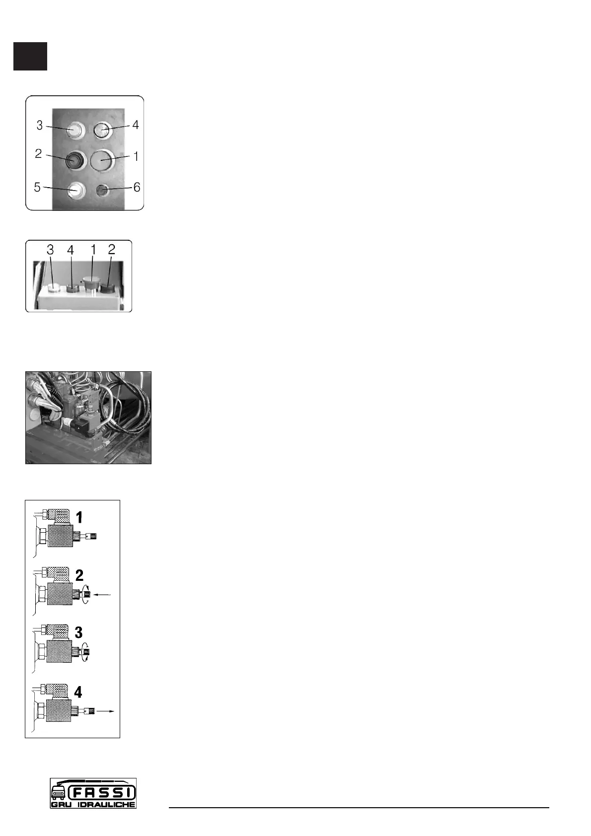
Layout of the control panel (fig. 19), placed next to the distributor of the
crane
pos. 1 - Stop button (STOP)
2 - Audible alarm push button (danger)
3 - Orange warning light (90% of the capacity has been reached)
4 - Red warning light (activation of the limiting device)
5 - White warning light (power on)
6 - Fuse
Layout of the control panel (fig. 20) placed on the double control side and
on top seat (version with hand-cable controls)
pos. 1 - Stop button (STOP)
2 - Audible alarm push button (danger)
3 - Orange warning light (90% of the capacity has been reached)
4 - Red warning light (activation of the limiting device)
If the white warning light 5 comes on, it confirms that the electric circuit is
active.
!NOTE! In the absence of electric power all crane functions will be
desactivated.
If the orange warning light 3 comes on during load handling, 90% of the
capacity (lifting moment) has been reached.
If during operation the red warning light 4 comes on, the activation value of
the lifting moment limiting device has been reached.
Any hidden danger situation for persons must be audibly alarmed by pressing
the push button 2.
When there are serious, imminent and dangerous conditions for persons and
things during load handling, operate on the stop button 1, which isolates all
crane functions.
H1.4 REACTIVATION button of crane functions
with standard distributor in the absence of the
electric power
Firstly remove the protection guard. Then unscrew the fixing screws (13 mm
hexagonal spanner).
On the distributor it has been installed an electro-valve with a manual locking
function (fig. 21) which allows to reactivate all the crane functions in case of
absence of the electric power. Only in these conditions it is permitted to remove
the lead seal which protects the device. Push the button and turn it into the
clockwise sense (fig. 22 pos. 1-2); the button stays in stable and closed position.
(!) When the electric power is restablished, remember to put the button in its
original position, turning it into the anti-clockwise sense. (fig. 22 pos. 3-4)
H1.3
CONTROLS TO
OPERATE THE CRANE
F 170A
26
fig. 22
fig. 21
fig. 19
fig. 20
 Loading...