H2.2 Lifting moment limiting device “INTELLIGENT TYPE” (optional)
This device utilises an electrohydraulic technology, preventing any movement which
causes an increase in the pressure induced by the load in the inner and outer rams
of the crane (and of the hydraulic extension if fitted), up to the “critical values”. These
values, which are non-exceedable, determine the intervention levels and provide the
data for setting the device.
The lifting moment limiting device concernes the following manoeuvres:
- Inner boom descent; the inner boom lift is controlled
by the general main pressure valve of the distributor.
- Outer boom lift and descent.
- Extension of extension boom sections.
- Winch rope lift (if fitted).
- If hydraulic extension is fitted: extension outer boom
lift and descent.
- Extension of the jib extension booms section.
Crane with standard distributor
The lifting moment limiting device is based on hydraulic controls
which are activated when the intervention value is reached and block
the movements of the relevant distributor levers in one or both direc-
tions. Please remember that the device will return the lever of the ele-
ment being used to neutral position. The condition of intervention is
operated by the position of the outer boom (or, if hydraulic extension
is fitted, the position of the extension outer boom), on which the electronic signal
position (mercury level switch) is read by a special electrovalve. This determines
the controls of the locking or unlocking (resetting) of the controls concerned.
Crane with Danfoss distributor (available on request)
The lifting moment limiting device system uses the specific functions of the distributor
by utilising an electro-hydraulic technology, it does not allow you exceed the set
value, by disactivating the controls (levers in neutral position) commanded by the limi-
ting device. The condition of intervention is operated by the position of the outer
boom (or, if hydraulic extension is fitted, the position of the extension outer boom), on
which the electronic signal position (mercury level switch) is read by a special electro-
valve. This determines controls which are locking or unlocking (resetting) of the con-
trols concerned. When the moment is reduced, it resets automatically (the manoeu-
vres blocked by the device are released). N.B.: There is a delay of four (4) seconds after the
moment reduction before the reset can occur in order to safeguard the stability of the device.
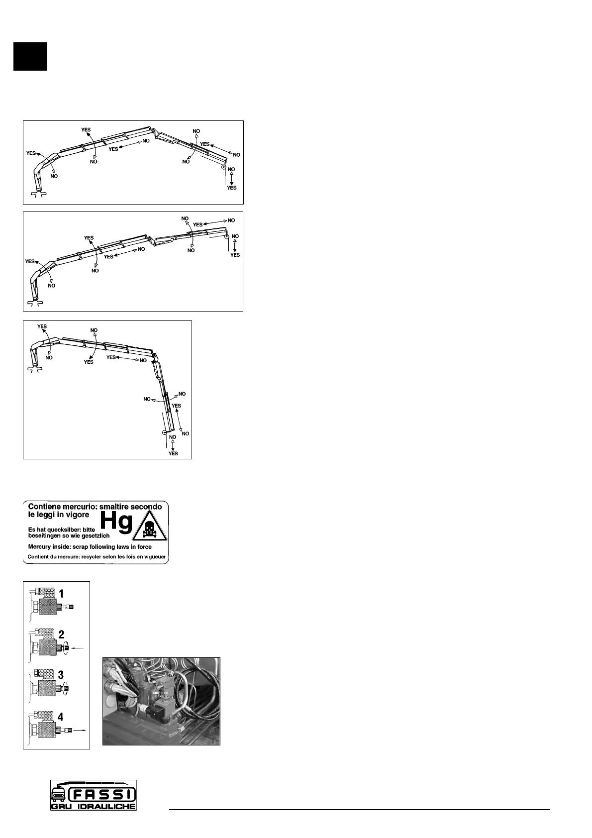
Fig. 18a-b-c illustrate the configurations of the crane (and of the eventual hydraulic
extension) with the manoeuvres allowed and not allowed by the device, in connection
with the horizontal position of the crane and extension outer booms.
(!) CAUTION DANGER (!)
On the outer boom there is a mercury capsule (mercury level switch) duly protected
and provided with the following warning stickers.
Mercury is extremely toxic. In case of replacement and/or scrapping, dispose
of or recycle the capsule containing mercury with maximum care, and in accor-
dance with the national regulations in force.
H2.3 REACTIVATION button of crane functions with
standard distributor in the absence of the electric
power
Firstly remove the protection guard. Then unscrew the fixing screws
(13 mm hexagonal spanner).
On the distributor it has been installed an electro-valve with a manual
locking function (fig. 21) which allows to reactivate all the crane func-
tions in case of absence of the electric power. Only in these condi-
tions it is permitted to remove the lead seal which protects the device.
Push the button and turn it into the clockwise sense (fig. 22 pos. 1-2);
the button stays in stable and closed position.
(!) When the electric power is restablished, remember to put the button in its
original position, turning it into the anti-clockwise sense. (fig. 22 pos. 3-4)
H2.3
CONTROLS TO
OPERATE THE CRANE
F 170A
30
fig. 18a
fig. 18b
fig. 18c
fig. 22
fig. 21
 Loading...