V
Victoria BellAug 14, 2025
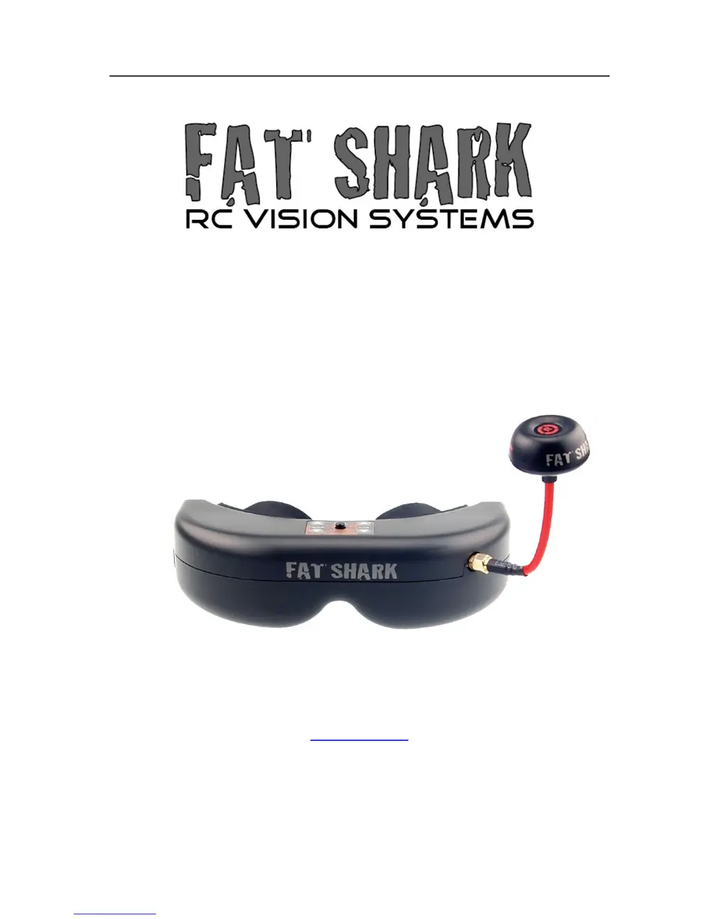
How to fix Fat Shark Accessories when there is no image and the display is completely dark?
- JJames WilliamsAug 15, 2025
If your Fat Shark accessories display is completely dark, it's likely due to a lack of power. Check all power connections to ensure they are secure and the device is receiving power.