EasyManua.ls Logo

FCI FLT93 Series User Manual

FCI FLT93 Series
12 pages
To Next Page IconTo Next Page
Page #1 background imageLoading...
Page #1 background image
This page is subject to proprietary rights statement on last page
FLT93 Installation, Operation and
Troubleshooting Guide
Pre-Installation
A. To get the best results from the instrument, the instrument should be mounted 20 pipe diameters downstream from any valve,
pipe elbow, or other flow disturbance and 10 pipe diameters upstream from any disturbances.
The instrument tag shows the model number, tag number (if noted on the customers order), serial number along with other
important safety information. Compare this information with the appropriate pipe installation drawings to verify the instrument
is the correct configuration.
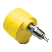
B. Verify the serial numbers on the enclosure(s), flow element and electronics match. The instrument may not work if the
serial numbers do not match. (The remote option has a remote transmitter enclosure (FT) and a local flow element enclo-
sure (FE). The integral option has one enclosure.)
Flow Element Serial Number
Also Showing Flow Arrow.
(Located near the FE enclosure.
It is also on the enclosure tag.)
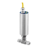
Electronics Serial Number
(It is also on the transmitters (FT) enclosure tag.)
C. Recommended installation/troubleshooting tools are an open-ended wrench to fit the NPT connection, an open-ended wrench
to fit the flanged fitting nuts and bolts, a small flat blade screw driver for manipulating potentiometers, both a medium flat
blade screwdriver and a medium phillips head screwdriver for tightening connections, 3 mm allen wrench for CENELEC
approved instruments, a measuring tape for proper flow element placement, and a DVM for Ohm/Voltage measurements.
Note:
If the instrument is a remote configuration, the serial number on the enclosure tags must match.
The recommended tag number on the local enclosure will have an FE in the tag number. The recommended tag number on the
remote enclosure will have an FT in the tag number. (Tags are specified by the customer, “FE/FT” is a recommended naming
convention.)
Tag Location - Between Conduit Ports
On Integral or Local Enclosure
Tag Location - Top Side of
Remote Enclosure Option

Questions and Answers:

FCI FLT93 Series Specifications

General IconGeneral
TechnologyThermal dispersion
Termination StyleTerminal block
Repeatability±0.5%
Process Connection1/2" NPT
EnclosureNEMA 4X (IP66)
ApprovalsFM, CSA, ATEX, IECEx
OutputSPDT relay

Summary

Pre-Installation

Tag Location - Between Conduit Ports

Shows tag location for integral or local enclosure options.

Tag Location - Top Side of Remote Enclosure Option

Shows tag location for remote enclosure options.

Flow Element Installation

Wiring Preparation

Wiring the Instrument

Jumper Placement

Standard Default Jumper Configuration

Details default jumper settings for various instrument functions.

Selectable Heater Wattage Control

Table showing heater wattage selection for different models.

Relay Contact Configuration

Describes relay contact options like SPDT and DPDT.

Relay Energization

Explains relay energization logic for alarms based on flow/level.

Input Power

Shows jumper settings for different input power ranges.

Alarm Adjustment Procedure

Control Circuit Adjustment Locations

Identifies adjustment potentiometers and LEDs on the control circuit.

Adjustment by Observation (Option 1)

Describes how to adjust alarms by observing indicator LEDs.

Flow Applications

Steps for adjusting flow alarms and setting parameters.

Level Applications

Steps for adjusting level/interface alarms and setting parameters.

Flow Alarm Procedures

Detecting Decreasing Flow

Procedure for setting low flow alarms with hysteresis.

Detecting Increasing Flow

Procedure for setting high flow alarms with hysteresis.

Temperature and Measurement Procedures

Detecting Increasing Temperature

Procedure for setting high temperature alarms with hysteresis.

Detecting Decreasing Temperature

Procedure for setting low temperature alarms with hysteresis.

Adjustment by Measurement (Option 2)

Describes how to adjust alarms using a voltmeter.

Air/Gas Flow Applications

Steps for setting up flow alarms for air or gas media.

Detailed Flow Alarm Setup

Detecting Decreasing Flow (low flow alarm)

Detailed steps for calculating and setting low flow alarms.

Detecting Increasing Flow (high flow alarm)

Detailed steps for calculating and setting high flow alarms.

Continue Air/Gas Flow Setup & Liquid Level Apps

Continue With the Air/Gas Flow Procedure

Final steps for air/gas flow alarm setup and verification.

Wet/Dry Liquid Level Applications

Steps for setting up level alarms for liquid media.

Detailed Level Alarm Setup

Detecting Dry Condition (low level alarm)

Detailed steps for calculating and setting low level alarms.

Detecting Wet Condition (high level alarm)

Detailed steps for calculating and setting high level alarms.

Troubleshooting

LED and Mode Switch Checks

Checks yellow LED status and mode switch position.

Signal and Power Supply Verification

Verifies signal voltage output and input power supply.

Sensor Element Checks

Checks sensor element connections for integral and remote installations.

Alarm Switch Point Settings

Verifies jumper settings related to alarm points.

Related product manuals