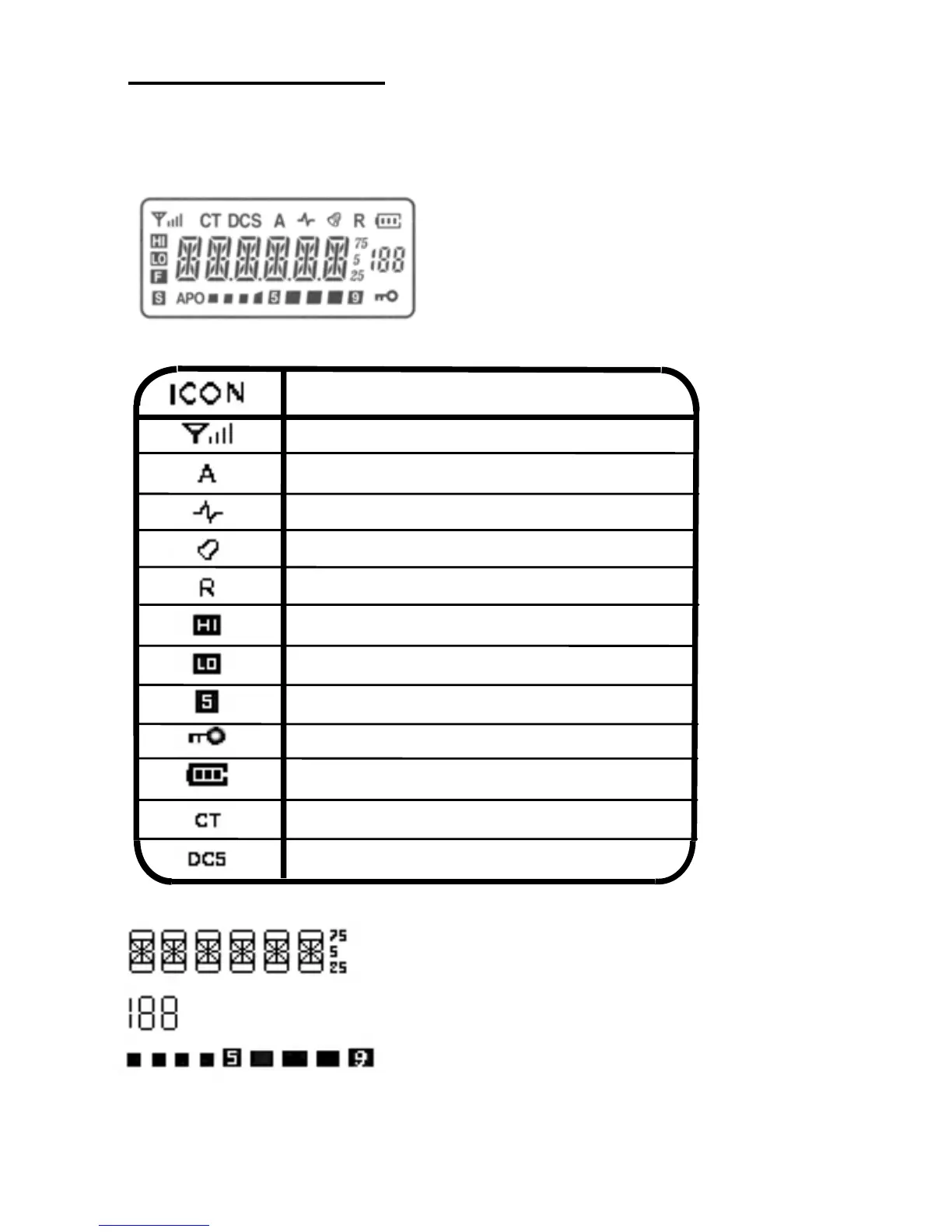
LCD DISPLAY
The locations of icons used in the LCD DISPLAY are shown in the
diagram below, their meaning is explained in the table following.
EXPLANTION
Signal scan indicator
Signal strength indicator
Turn speaker on / off
Turn sound on / off
Reverse frequency
High power output
Low power output
Battery save
Keypad Lock
Battery level indicator
CTCSS
DCS
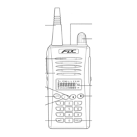
Displays the working frequency and other function
selections
Displays the memory channel number in MR mode
Displays the power output while transmitting
8