4
Mounting the PMA
4. Lay packaged pump on a at, open surface and
remove the package.
5. Flatten pump packaging and lay the PMA on the
end of the pump in preparation for mounting.
6. The PMA mounting hardware kit (# 152350902)
is attached to the PMA packaging. It contains
a gasket, a tube of grease, and four 5 / 16" cap
screws with lockwashers.
7. Remove the two packaging ends and the
protective sleeve from the PMA.
8. Apply grease provided to the inside wall of the
pump motor electrical connector, and the rubber of
the lead assembly connector.
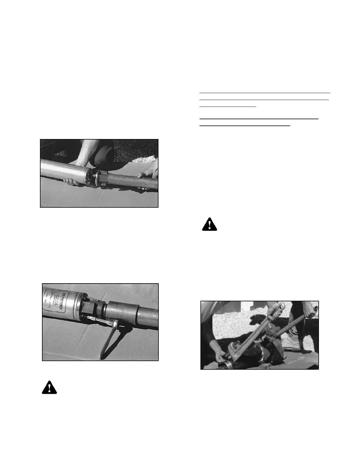
9. Place the gasket on the end of the PMA, aligning
locating pin and bolt holes (Figure 1).
Figure 1: Aligning Pins
10. Mount PMA onto discharge head by aligning
locating pin on PMA with hole in discharge head,
assuring that the lead assembly in the motor
discharge head is seated in its notched position,
and that the PMA gasket is properly in place.
11. Tighten PMA onto discharge head using four cap
screws and lock washers supplied. A cross bolt-
tightening pattern is recommended for securing
PMA (Figure 2).
Figure 2: Tighten Bolts
The motor discharge head must not be
rotated more than one full rotation in
either direction. Rotation could cause
damage to the electrical connections
in the conduit, creating a risk of lethal
electrical shock or equipment failure.
Note: Before assembling the PMA to the discharge
casting make sure the wire lead is properly set
and aligned in the discharge casting. Improper
alignment could damage the wire lead or motor
pins. Failure to push PMA up snug against the
discharge casting before tightening cap screws, or
failure to use a cross-pattern while tightening the
bolts could break the discharge casting or strip the
threads in the PMA.
Note: IST units without a VS4 sufx and STP units with a
VS2 sufx can only be electrically connected to an
IST-VFC or MagVFC.
STP or IST units with a VS4 sufx can only be
electrically connected to a MagVFC. Unlike FE
Petro’s standard pumps, the following pumps
cannot be interchanged with competitive models:
The variable speed PMA VS2 (which is part of IST •
units without the VS4 sufx or the STP units sufxed
with VS2)
The PMA VS4 (which is part of the IST and STP •
units with the VS4 sufx)
12. Apply a non-hardening, UL classied, gasoline-
resistant pipe sealing compound to the riser pipe
threads, if not already installed.
Failure to use a proper thread sealing
compound could result in a lack of
seal where the riser threads into the
tank opening, making it impossible to
perform a tank-tightness test. This may
also create a potential site for fuel to
leak into the environment and / or the
containment sump.
13. Slide riser over the PMA and tighten into manifold
threads (Figure 3). Maximum riser size is found
by taking the grade to tank mounting thread
measurement and subtracting the manifold height
and clearance (6" clearance recommended).
Figure 3: Attach Riser
Note: Riser material required for pump is 4.5" outside
diameter with a .188" wall. Minimum riser length
supplied by FE Petro is 7".
Warning
Warning
 Loading...