5
Example
Grade to tank mounting threads (bury depth) 48"
Minus manifold height without leak detector
(w / leak detector height = 12.50)
-11"
Minus 6" for top clearance (2" minimum) -6
= Maximum riser size 31"
Length Setting
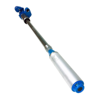
14. Cut wire tie(s) securing the motor wire at the top of
the pump; lay the wires out above the pump head
so that wires can feed through conduit freely when
setting length (Figure 4).
Figure 4: Cut Wires
Failure to cut wire ties prior to setting
pump length could result in damage to
electrical motor wires, presenting a risk
of lethal electrical shock or equipment
failure.
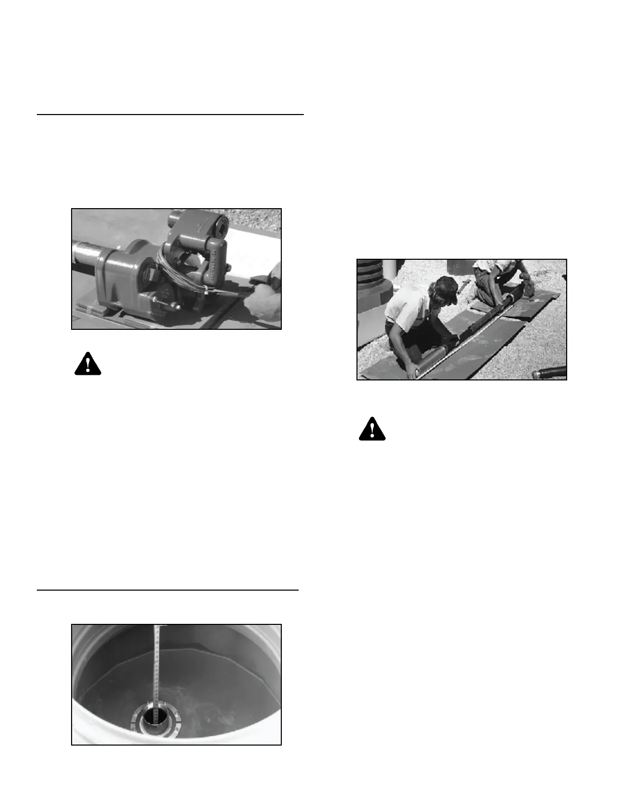
15. Measure from the bottom of the tank to the top of
tank mounting threads. Subtract the distance for
clearance between the PMA and the bottom of the
tank (6" recommended). This is the length to which
the pump should be extracted, measured from the
bottom of the riser threads to the bottom of the
motor end bell.
Note: 6" clearance provides a 5" clearance from the
pump motor end bell to the bottom of the tank once
the riser is screwed into tank mounting threads.
Tank + thread measurement 96"
Distance from bottom (5") + riser thread
engagement (1")
-6"
= Length (bottom of riser to end bell) 90"
Figure 5: Measure Tank
16. Hold the manifold securely to the surface to
prevent damage while setting length.
To allow movement of the telescoping pipe,
verify that none of the pipe coupling setscrews
are in contact with the pipe. Lay a tape measure
out to accurately measure the distance from the
bottom of the riser to the bottom of the pump
motor end bell.
17.
Grasp the pump just above the PMA and pull rmly,
extending to the length required (from Step 15).
Note: Use care to ensure electrical conduit wires
at the top of the discharge manifold are not
damaged during length setting. If column pipe
is extended beyond desired length have a
second person retract conduit wires as column
pipe is shortened. This will prevent damage to
conduit wires.
Figure 6: Measure Riser
The motor discharge head must not be
rotated more than one full rotation in
either direction. Rotating could cause
damage to the electrical motor wires,
presenting a risk of potentially lethal
electrical shock or equipment failure.
Note: O-ring seals inside the locking coupling may have
sealed to the column pipe during shipping. Spin the
motor discharge head slightly (not more than one
full rotation) while pulling to loosen the O-ring seals.
Warning
Warning
 Loading...