6
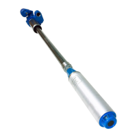
18. Once the length is correct, lock the STP length by
tightening all three coupling setscrews. Tighten the
setscrews nger-tight, making sure they come into
contact with the pipe (Figure 7).
19. Tighten each setscrew an additional full turn
minimum. The head of the setscrews should be
ush or below ush with the outer surface of the
coupling (Figure 8).
Setscrews
3 places
Figure 7: Install Setscrews
5 / 32"
Allen
Wrench
Figure 8: Tighten Setscrews
Failure to properly tighten the coupling
setscrews at this stage could present
a risk of death, serious bodily injury
and / or equipment damage due to
movement of pipes during installation.
PMA Wiring
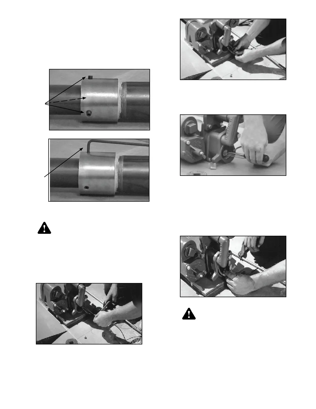
20. Measure approximately 6" of wire from the
discharge manifold; cut off excess wire and
discard (Figure 9).
Figure 9: Measure and Cut Wire
21. Place the three wires through the contractors plug
assembly (from hardware pack p / n 400301903)
as shown in gure 10.
Figure 10: Wire Through Contractor’s Plug
22. Using the screwdriver slide the contractors plug
into its seat in the discharge manifold. Tighten the
two screws in the contractor plug to secure it in
place (Figure 11).
Figure 11: Attach Contractor’s Plug
23. Strip the wire insulation back approximately 3 / 8"
on the three motor leads. Using the wire nuts
supplied (from hardware pack p / n 400301903)
connect to the wires from the electrical connector
orange to orange, black to black, and red to red.
24.
Coil the wires and push into the discharge manifold
cavity using care to ensure wires are not damaged
on discharge manifold threads (Figure 12)
.
Figure 12: Push Wires into Cavity
Damage to the electrical conduit wires
creates a risk of lethal electrical shock
and equipment failure. Do NOT use
equipment if electrical wires have
been damaged (contact FE Petro for
assistance).
25. Tighten the discharge head cover (from hardware
pack p / n 400301907) in place using a 3 / 4" ratchet
or breaker bar (Figure 13).
Warning
Warning
 Loading...