7
Figure 13: Tighten Discharge Head Cover
Secure to Tank
Note: The bottom end-bell of the PMA is not designed
to support the weight of the entire pump. Resting
or dropping the pump on this end-bell may
damage the plastic end-bell and the plastic pump
components inside. This type of damage is not
considered a manufacturing defect under FE
Petro’s warranty.
26. Measure the pump, from the bottom of the
threaded riser to the bottom of the pump-motor,
and compare this to the tank measurement,
measured from the mounting ange to the inside
of tank bottom. The STP / IST and riser are sized to
place the intake (at the bottom of the pump-motor)
approximately 5 inches off the bottom of the tank.
If the difference between the bottom of the pump
motor and the bottom of the tank is more than
6 inches or less than 4 inches, verify that this is
the correct pump for this tank installation. If it is
not the correct pump and is outside the above
specications, contact FE Petro, Inc. sales
representative or the FE Petro, Inc. factory.
27. Apply a non-hardening, UL classied, gasoline-
resistant pipe sealing compound to the riser pipe
threads.
Failure to use a proper thread sealing
compound could result in a lack of seal
where the riser threads into the tank
opening, making it impossible to perform
a tank-tightness test. This may also
create a potential site for fuel to leak into
the environment and / or the containment
sump.
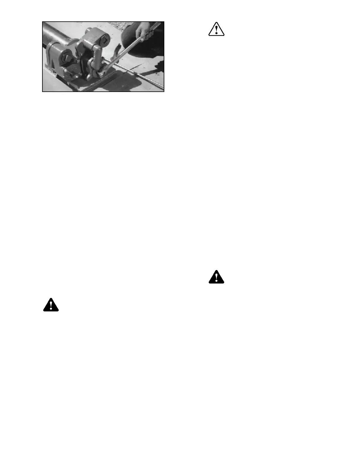
28. Carefully lower the unit into the tank, and engage
the threaded riser of the pump into the threaded
ange on the tank. Tighten the riser into the tank
using a large pipe wrench until a water / air tight
joint has been made. Do this by turning in the
tightening (clock-wise) direction only.
Turning the pump in the loosening
direction during the tightening process
may scrape away the thread sealing
compound, making it impossible to
perform a tank-tightness test. This may
also create a potential site for fuel to
leak into the environment and / or the
containment sump.
29. Connect the supply line piping to the discharge
port in the discharge manifold assembly. The
discharge port is the 2-inch NPT vertical opening.
30. Connect the electrical conduit with approved
ttings per NFPA 30, NFPA 30A, and NFPA 70 to
the junction box (see Figure 15).
31. Remove the junction box cover (see Figure 15),
and remove the compression seal (contractors
plug) by loosening the screw(s) (do not remove
screw). A four hole compression seal (contractors
plug) is provided on all units,
On single phase units, two power wires, one •
ground wire and a blank (with celcon rod
supplied to ll forth hole).
For three phase units, three power wires and •
one ground wire.
32. Verify that the power is still OFF at the supply box.
33. Pull wires from power supply into the junction
box and feed through the compression seal
(contractors plug).
34. Replace the compression seal and tighten
into place securely. All wiring must be done in
accordance with the National Electrical Code
(NEC) and any other local, state, or federal
regulations required.
The compression seal (contractors
plug) is not intended to replace the
vapor explosion seals required by
the NEC. All materials used between
the power supply box and the pump
junction box must be gasoline and oil
resistant. Failure to comply with these,
and all applicable NEC guidelines,
could result in an unsafe installation.
35A. SINGLE PHASE UNITS: Connect the ground wire
to the lug in the junction box; using the wire nuts
supplied (from hardware pack p / n 400301901)
connect the wires from the power supply to the
orange and black wires in the junction box. A
capacitor is required and color-coding is not
necessary.
Warning
Caution
Warning
 Loading...