Ethernet-I/P Fieldbus Expansion Unit
PAGE 24
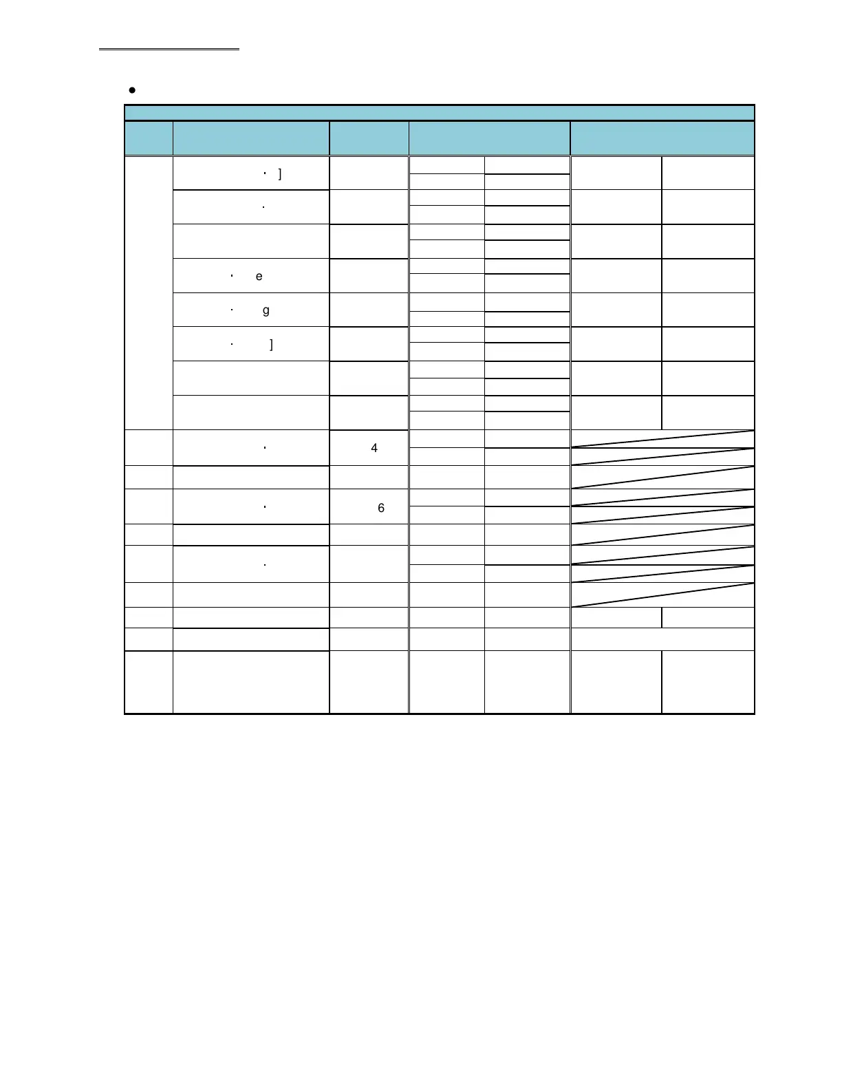
● Message Information Output Example (Spindle Format)
(Note:PLC output ref. for Allen Bradley)
Spindle Format
Spdl.
No.
Output Item
Result
Output
PLC Input (BCD Format)
PLC Input (ASCII Format)
1
Peak Torque [N
・
m]
12.34
C00 00 12
C00 to
C07
‘_12.34__’
C01 34 02
Final Torque [N
・
m] 12.34
C02 00 12 C08 to
C15
‘_12.34__’
C03 34 02
Final Angle [deg] 123.4
C04 00 12 C16 to
C23
‘_123.4HX’
C05 34 01
Rate 1 [N
・
m/deg] 1.234
C06 00 12 C24 to
C33
‘__1.234___’
C07 34 03
Rate 2 [N
・
m/deg]
5.678
C08 00 56
C34 to
C43
‘__5.678___’
C09 78 03
Rate 3 [N
・
m/deg] 9.012
C10 00 90 C44 to
C53
‘__9.012___’
C11 12 03
1st Time [sec] 12.345
C12 01 23
C54 to
C63
‘_12.345___’
C13 45 03
2nd Time [sec] 6.789
C14 00 67 C64 to
C73
‘__6.789___’
C15 89 03
2
Peak Torque [N
・
m] 23.45
C16 00 23
C17 45 02
~
~
~
~
~
3
Peak Torque [N
・
m]
34.56
C32 00 34
C33 56 02
~
~
~
~
~
4
Peak Torque [N
・
m]
45.67
C48 00 45
C49 67 02
~
~
~
~
~
Free area C74 C74
~
~
~
~
~
~
Final Message Information
Area
(when max 4096 bytes
setup)
C4095 C4095
* (20H) is the space code (space).
Note: Each spindle’s data will reside in the same location regardless of whether the spindle is used in a
particular fastening cycle.
(Example: If a system has 3 connected spindles and spindle #1 is not used in a sequence (for a particular
model for example), then the data for spindle #2 & #3 will only be sent and will reside in their spindles data
location skipping the spindle #1 location)
 Loading...
