MSS
TM
Series
© Copyright 2022 Fluid Equipment Development Company | www.fedco-usa.com
- 26 -
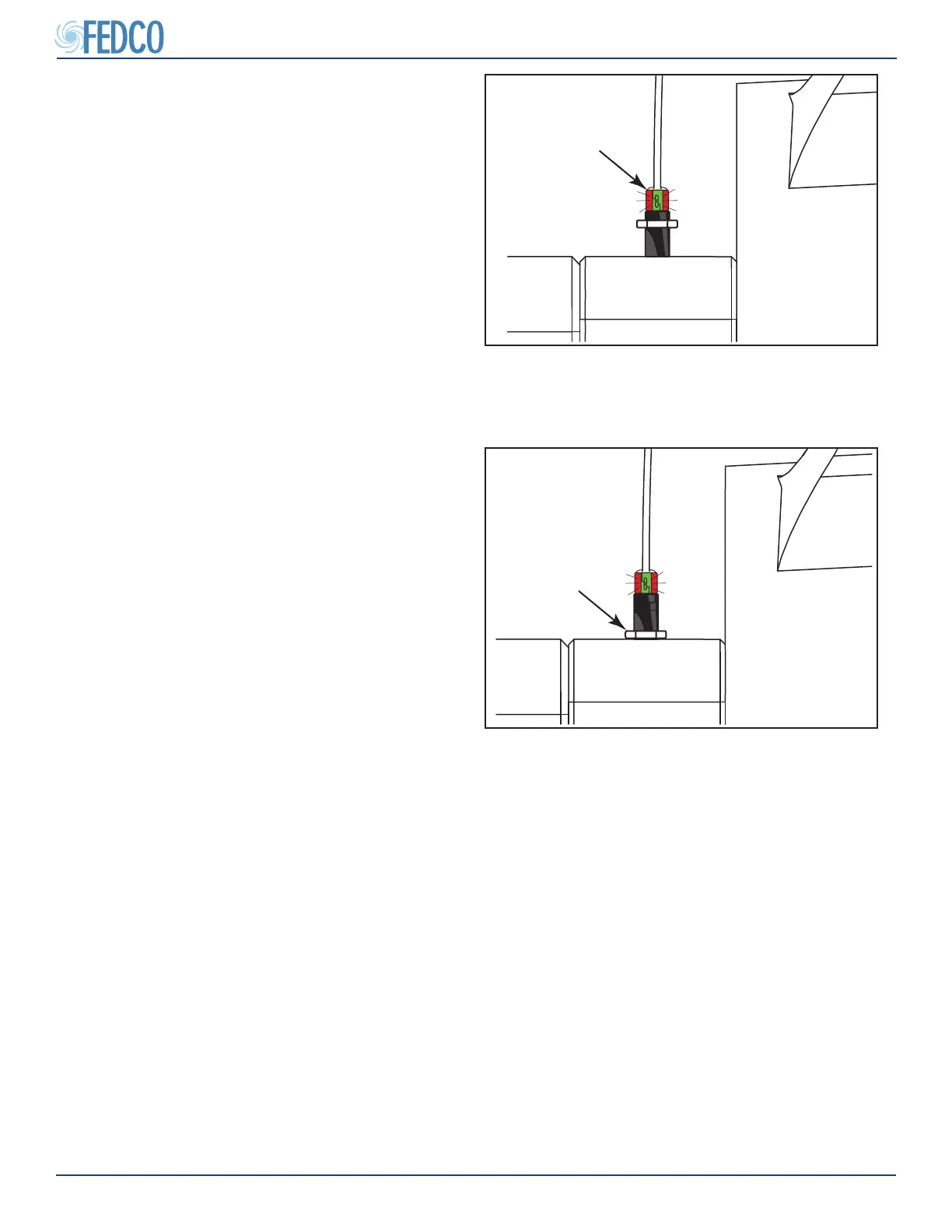
Figure 46 - Tightening Adjustment Locknut
TIGHTEN
ADJUSTMENT
LOCKNUT
4. Tighten the adjustment locknut to prevent
sensor movement.
NOTES: If a false shut down occurs after the
adjustment procedure, loosen the adjustment
locknut and rotate the sensor a further one-
quarter (1/4) turn to ensure no mis-adjustment
has occurred.
5. Once the sensor is properly adjusted, dis-
connect the sensor from the temporary
power supply and permanently connect the
sensor to the VFD.
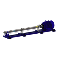
Figure 45 - Adjusting Shaft Position Sensor
ROTATE 1/4 TURN
AFTER SENSOR
ILLUMINATES
3. Slowly rotate the sensor clockwise until the
sensor becomes illuminated with a green
and red light. Once the sensor is illuminat-
ed, rotate the sensor a further one quarter
(1/4) turn.
Pump Overhaul Continued