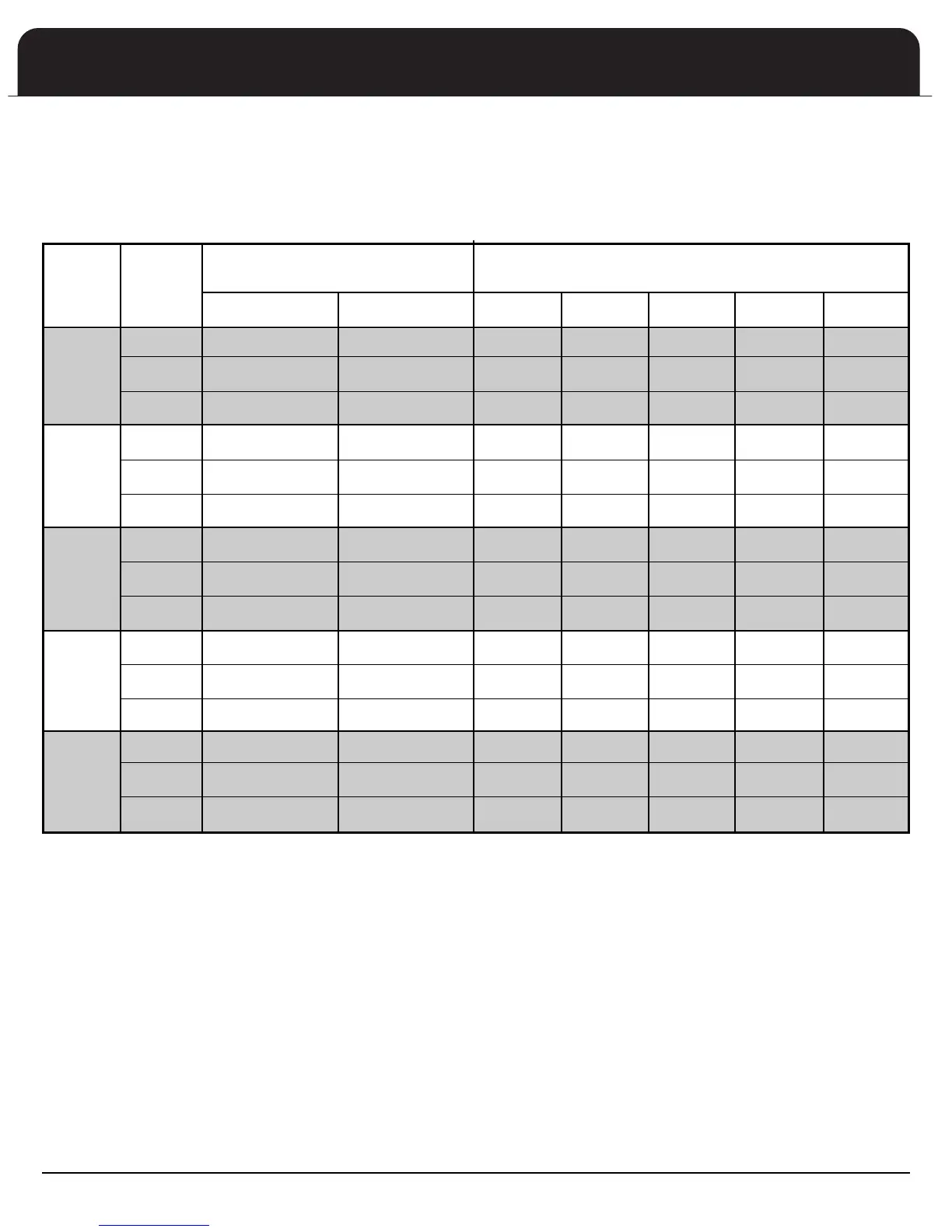
11
UNIT
MOTOR
SPEED
.2 .3 .4 .5 .6
HIGH 15 kW @ 0.20" 10 kW @ 0.15" 925 900 850 795 690
MEDIUM 15 kW @ 0.20" 5 kW @ 0.15" 800 760 745 670 N/A
LOW 10 kW @ 0.15" N/A 655 625 600 N/A N/A
HIGH 15 kW @ 0.20" 10 kW @ 0.15" 905 880 830 780 680
MEDIUM 15 kW @ 0.20" 5 kW @ 0.15" 785 735 730 655 N/A
LOW 10 kW @ 0.15" N/A 645 615 590 N/A N/A
HIGH 20 kW @ 0.25" 10 kW @ 0.15" 1440 1350 1260 1180 1040
MEDIUM 20 kW @ 0.20" 10 kW @ 0.15" 1300 1220 1050 940 860
LOW 20 kW @ 0.15" N/A 1160 1070 950 880 780
HIGH *20 kW @ 0.60" 15 kW @ 0.45" 1680 1640 1590 1520 1430
MEDIUM *20 kW @ 0.50" 15 kW @ 0.40" 1440 1410 1380 1340 1250
LOW *20 kW @ 0.40" 15 kW @ 0.40" 1240 1220 1190 1150 1100
HIGH *20 kW @ 0.60" 15 kW @ 0.45" 2230 2105 1990 1895 1725
MEDIUM *20 kW @ 0.50" 15 kW @ 0.40" 1950 1930 1840 1770 1590
LOW *20 kW @ 0.35" 15 kW @ 0.35" 1360 1350 1340 1185
1080
Air flow shown at the following conditions:
• No heat elements in air handler
• Decrease CFM 1% for 5 kW, 7.5 kW, or 10 kW heat kits. Decrease CFM 2% for 15 kW or 20 kW heat kits
• 60 Hertz — 230 volts. Decrease CFM 6% for 208 volt operation
• Standard air handler filter.Dry coil airflow shown
BLOWER SPEED / STATIC OPERATION TABLE
*Specifications applicable to upflow and horizontal applications
AFPA24A1
AFPA24B1
AFPB36A1
AFPC48A1
AFPC48B1
AFPC60A1
AFPC60B1
R
ESISTANCE HEAT
STATIC PRESSURE (IN. WC) ACROSS
H
EAT ELEMENT @ MAX. CFM
60 Hz OPERATION
CFM @ EXTERNAL DUCT STATIC (IN. WC)
RESISTANCE
HEAT ONLY
AUXILIARY HEAT STAGED
WITH HEAT PUMP
Motor Speed
C
orrect heating and cooling motor speeds MUST be used for proper operation. Refer to the Blower Speed/Static Operation Table
b
elow for correct cooling speed and for minimum allowable heating speed.