9
9
19
19
8
8
5
47
47
52
52
52
52
90
90
90
90
90
90
98
98
98
98
98
98
103
103
103
103
103
103
103
103
103
103
103
103
103
103
107
107
107
107
107
107
107
107
7
6
2
1
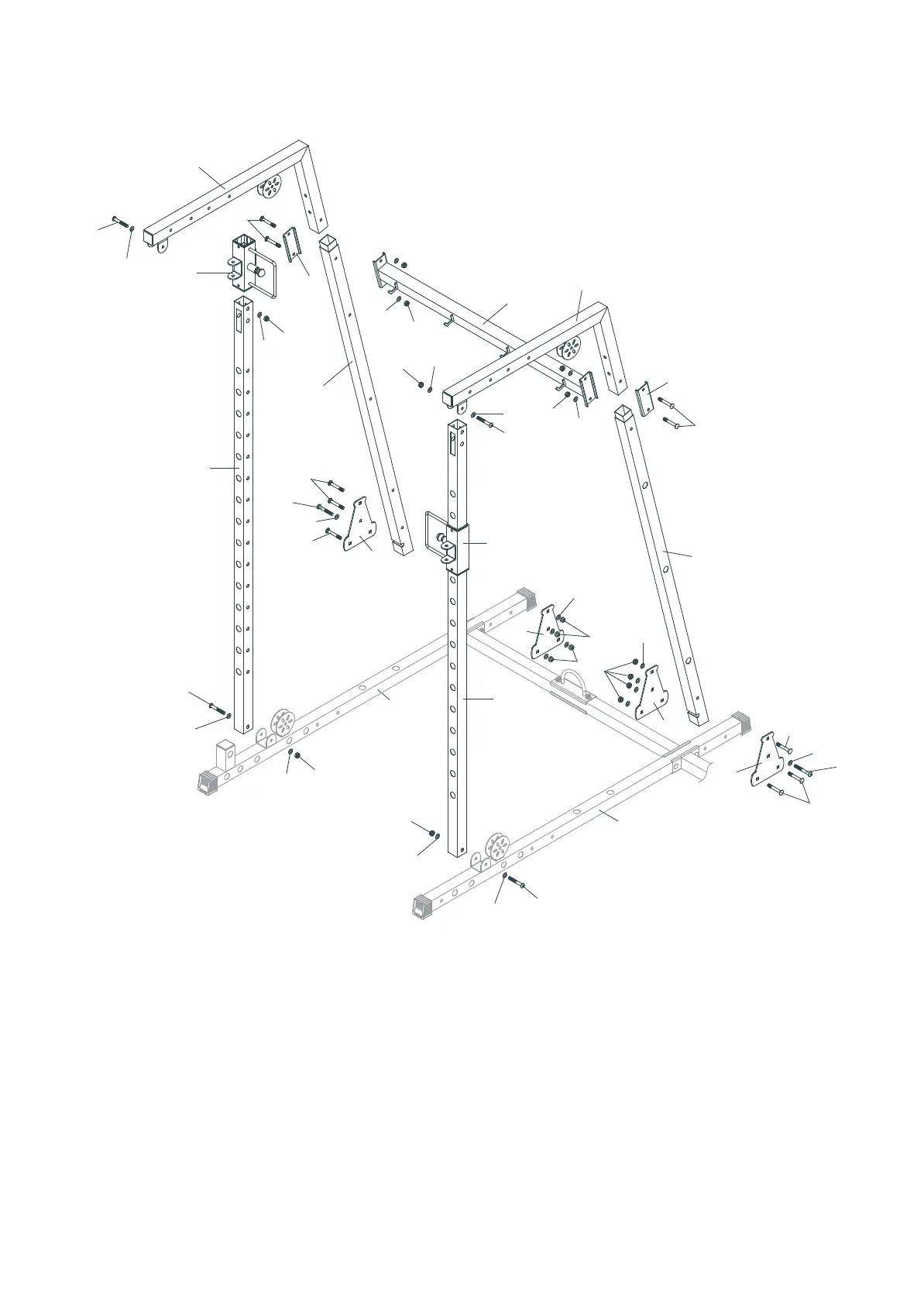
STEP 2˖
1. Attach the two Support Frames (9) to the Bottom Tube (Right & Left) (1&2), using two
M10X70 Bolts (90), four M10 Washers (103) and two M10 Nylon Nuts (107).
2. Slide Slide Assembly (19) onto two Support Frames (9).
3. Attach the Rear Upright Frame (Right & Left) (6&7) and four Special-Shaped Plates
(Square Hole) (52) to the Bottom Tube (Right & Left) (1&2), using six M10X70mm
Carr
iage Bolts (98) two M10X70mm Bolts (90), ten M10 Washers (103) and eight M10
Nylon Nuts (107).
4. Attach the two Upper Cross Beams (8) to the two Support Frames (9), using two
M10X70mm Bolts (90), four M10 Washers (103) and two M10 Nylon Nuts (107).
5. Attach the Upper Connection Tube (5) and two Folded Edge Plates (47) to the Upper
Cross Beams (8) and Rear Upright Frame (Right & Left) (6&
7), using four M10X70mm
Carriage Bolts (98), four M10 Washers (103) and four M10 Nylon Nuts (107).
-5-
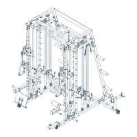
ASSEMBLY INSTRUCTIONS
 Loading...