VEK M1H_DE_GB_FR_NL_IT_ES.docx 19.05.2017 Copyright 2017 by FEIG ELECTRONIC GmbH
3.3 Output of loop frequency
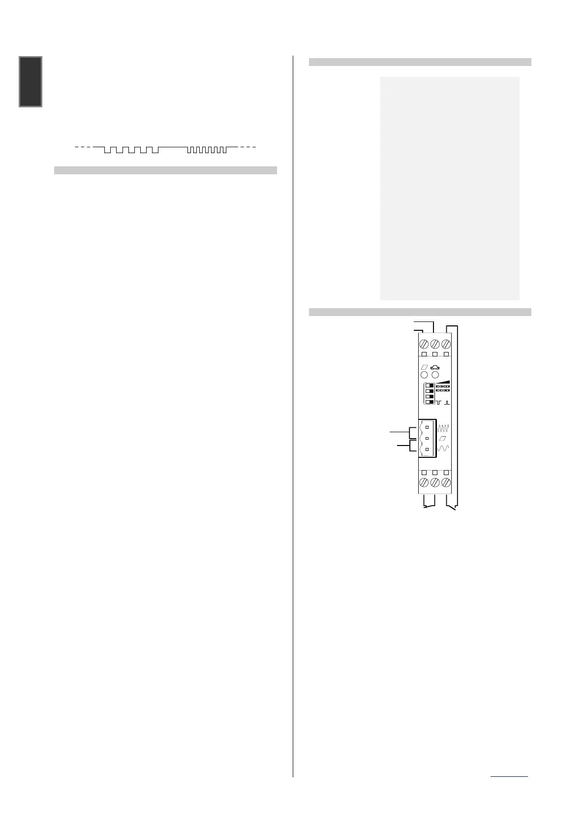
Approx. 1 sec. after calibration of the detector the loop frequency will be
displayed by pulse signals of the green LED. Firstly the 10 kHz position
of the frequency value will be indicated. For every 10 kHz frequency
value the green LED flashes once. After a break of 1 sec the 1 kHz
position is displayed in the same manner. If there is value of '0' in the 1
kHz position there will be displayed 10 flashes. The flashes for 1 kHz
position are a little bit shorter than for the 10 kHz position.
Example for 57 kHz loop frequency:
4 Safety information and warnings
The device should only used for the applications described by the
manufacturer.
Please keep this operation instruction always accessible and hand it
over to every user.
Inadmissible modifications to the device, use of repair parts and
supplementary equipment which are not sold or recommended by the
manufacturer can cause burning, electric shock and injuries.
Therefore the manufacturer has no liability and this excludes all
demands of warranty.
The warranty regulations of the manufacturer are valid in the version
of the purchase date for that device. There is no liability for not
suitable, wrong manual or automatic adjustments also regarding no
suitable applications of the device.
Repairs may only made by the manufacturer.
The power supply must be fulfill the requirements for SELV and
limited power sources according to EN 60950-1.
All connections, the start-up, maintenance, measurements and
adjustment operations to the detector have to be made from electrical
specialists who have special know-how in the prevention of accidents.
For the use of devices which have contact to electrical power, please
pay attention to the valid security instructions and all prevention
orders of fire and accidents.
The user is responsible for an installation, which has conformity to all
technical rules in the country where the device is mounted, and also
to all regional valid orders. For that the dimension of cabling, fuse
protection, connection to ground, switch off, disconnection, isolation
controlling and the protection for overload current have to be regarded
in detail.
The detector can not be used as a security device regarding to the
security instructions of electrical machines. Using in systems with high
danger potential it is necessary to include additional protection
devices!
All work on the device must be carried out in accordance with the
national electrical codes and regional regulations.
5 Technical data
79 x 22,5 x 90 mm (h x w x d without plug)
24 V AC/DC 10 % max.1,5 W SELV
25-800 µH, recommended 100-300 uH
0,01 % up to 0,65 % (f/f) in 4 steps
0,02 % up to 1,3 % (L/L)
max. 20 Ohm (incl. loop lead)
Relays
presence relay
pulse relay
250 mA / 24 V AC/DC (min. 1 mA/5 V)
contact n.c. (adjust. operation principle)
contact n.o.
40 ms (reaction time 80 ms)
screw terminals (power supply, relays)
binder plug (loop connection)
6 Connections
relay operation principle
Note
The information in this instruction can be changed without previous
announcement.
With this description all previous issues lose their validity.
The summary of information in this description was done with all
possible acknowledge and by the best conscience.
FEIG ELECTRONIC can’t give guaranty for the correctness of all
information. Particularly there is no liability by FEIG ELECTRONIC for
damages which result from a wrong installation of the device.
In spite of all efforts to correctness we are very thankful for every point
to a mistake in this description.
The installation recommendations in this description are based on
optimum conditions. For wrong environment conditions FEIG
ELECTRONIC doesn’t give a warranty to optimum operation of the
detector.
You can dowload the EC declaration of conformity and other important
documents from www.feig.de.
Note
The information in this instruction can be changed without previous
announcement.
With this description all previous issues lose their validity.
The summary of information in this description was done with all
possible acknowledge and by the best conscience.
FEIG ELECTRONIC can’t give guaranty for the correctness of all
information. Particularly there is no liability by FEIG ELECTRONIC for
damages which result from a wrong installation of the device.
In spite of all efforts to correctness we are very thankful for every point
to a mistake in this description.
The installation recommendations in this description are based on
optimum conditions. For wrong environment conditions FEIG
ELECTRONIC doesn’t give a warranty to optimum operation of the
detector.
 Loading...