Do you have a question about the Feig Electronic VEK S4 and is the answer not in the manual?
Detects metallic vehicles using an LC oscillator and switches output based on function.
Explains automatic calibration performed on power-up or button press.
Details two classification modules, vehicle data, and 8+1 class definitions.
Lists functions assignable to each of the four Open Drain outputs.
Explains loop multiplexing and detector synchronization to prevent interference.
Details setting the working frequency to prevent cross-coupling between loops.
Explains how to change the multiplexing sequence for cross-coupling prevention.
Covers setting head gap, amplitude factor, and loop length for classification.
Lists the settable output modes for the four open collector outputs.
Explains setting on-delay, minimum on duration, and off-delay for outputs.
Details baud rates and parity settings for the RS485 interface.
Lists supported CANopen baud rates and CiA standard compliance.
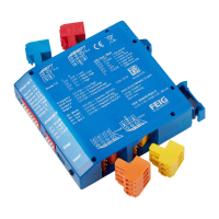
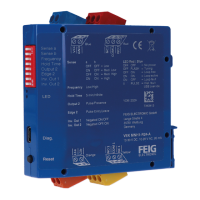
Covers physical installation, grounding, and setting unique detector addresses.
Details RS485 baud rate, bus termination, and loop assignment.
Explains setting head gap, amplitude factor, and loop length for calibration.
Comparing and adjusting displayed vs. actual vehicle lengths.
Measuring vehicle speed accurately and adjusting it.
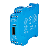
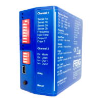
Describes the front panel LEDs and their normal operation behavior.
Explains functions activated by the M-key, including resets and settings display.
Details the procedure to restore the detector to its factory default parameters.
Indicates correct synchronization of multiple detectors via LED scrolling.
Explains the function of DIP switches for address and bus termination settings.
Provides the physical dimensions of the detector enclosure.
Step-by-step guide for opening and closing the detector enclosure.
Details power supply, interface connections via terminals and ribbon cable.
Pinout diagram for the 2x5-pole ribbon cable connector.
Explains the PE connection for noise immunity and surge protection.
Details the contents of the VEK M4D connection kit.
Mentions the software used for detector parameterization.
Explains scanning speed dependency on loop channels and interference filter.
Details setting the sensitivity for each channel in 256 steps.
Describes modifying switching hystereses for vehicle detection.
Explains setting separate holding times for each detector channel.
Details parameterizable logic modules for direction-dependent vehicle recording.
Shows evaluation logic for various traffic situations like single vehicle, traffic line, etc.
Table showing direction logic outputs for single vehicle scenarios.
Table showing direction logic outputs for traffic line scenarios.
Table showing direction logic outputs for wrong-way driver scenarios.
Table showing direction logic outputs for wrong-way driver scenarios.
Table showing direction logic outputs for maneuverer scenarios.
Table showing direction logic outputs for maneuverer scenarios.
Table showing direction logic outputs for wrong-way traffic scenarios.
Table showing direction logic outputs for cross-traffic scenarios.
Explains direction logic for short entrances/exits and suppresses count compromise.
| Brand | Feig Electronic |
|---|---|
| Model | VEK S4 |
| Category | Security Sensors |
| Language | English |