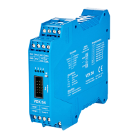
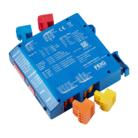
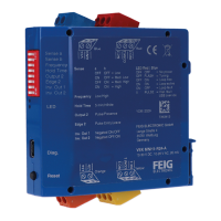
Manual VEK S4
16 03/09 FEIG ELECTRONIC GmbH
4.4 Synchronisation display
Correct function of the synchronization of multiple detectors is indicated by the scrolling effect of the LEDs in
an 8s rhythm. As the device address increases from left to right, the scrolling LEDs also run from left to right
for all synchronized detectors.
Polling of the Master detector is also possible, as described in 4.2 (M)ode button. The Master sends the
synchronization signals over the ribbon cable to the other detectors (Slaves). Selection is random.
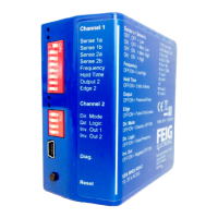
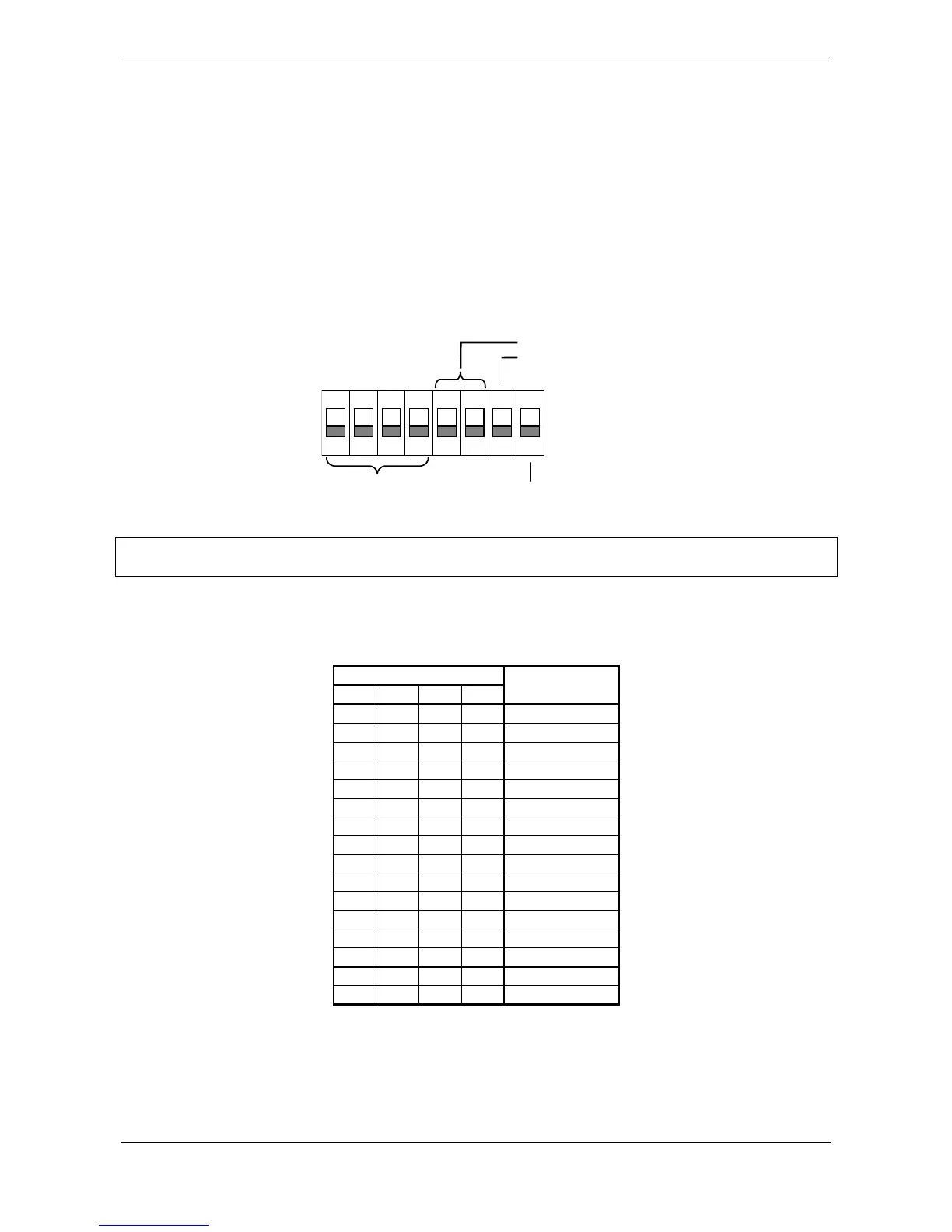
4.5 DIP switches
The 8-pole DIP switch is used for selecting the device address and for enabling termination for the CAN bus
and RS485 interface. The DIP switches are located inside the enclosure. As shipped all DIP switches are in
the OFF position.
1
2 3 4 5 6 7 81
ON
Address
0-15
RS485
Pullup / Pulldown
Bus termination
CAN
Bus termination
Note! Before startup check all DIP switches for the correct position! Improper setting can damage
the interfaces.
4.5.1 Device address
The device address results from the hardware device address set using the DIP switches and the software
settable address offset.
DIP switch
1234
Hardware
device address
0000 0
1000 2
0100 4
1100 6
0010 8
1010 10
0110 12
1110 14
0001 16
1001 18
0101 20
1101 22
0011 24
1011 26
0111 28
1111 30
Device address = Hardware device address + Address offset
For downward compatibility to VEK S3 the step size for address offset is 2
 Loading...