Do you have a question about the Feig Electronic VEK MNE1 and is the answer not in the manual?
Explains how the LC oscillator detects vehicles in the loop region.
Describes loop channel adjustment after power-on or button press.
Details available output signals like presence, pulse, direction, or loop error.
Explains how VEK MNE2 prevents loop interference by sequential activation.
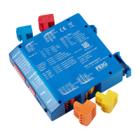
Advises installing the detector in a switchboard, protected from humidity and dust.
Details the pin configuration of the 11-pin round plug for different models.
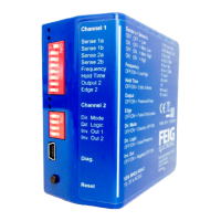
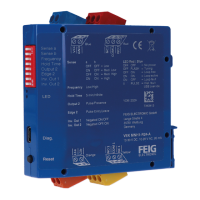
Explains the function of the two LEDs for indicating loop channel status.
Describes functions triggered by pressing the reset button on the front panel.
Details the settings defined by the DIP-switches on the detector's front panel.
Explains the use of the USB socket for parameter definition and diagnostics.
Covers selecting sensitivity in 255 steps, optimizing for minimal interference.
Explains adjusting switching hysteresis to prevent busy signal dropout for certain vehicles.
Discusses adjusting operating frequency to avoid coupling effects between adjacent loops.
Details setting hold times from 1 to 255 minutes or infinite for each channel.
Lists selectable signal shapes for the outputs: presence, pulse, continuous, or general fault.
Allows selection of inverted or non-inverted signal output for open-circuit or closed-circuit principle.
Specifies how the loop channel behaves and what the output assumes during a loop fault.
Covers assigning outputs to loop channels or specific directions when direction detection is active.
Explains selecting signal shapes for outputs when set to pulse output.
Details adjusting output signal timing properties like on delay, off delay, and minimum duration.
Describes enabling and configuring direction detection for the 2-channel traffic detector.
Presents various evaluation logics for direction detection based on traffic situations.
| Category | Security Sensors |
|---|---|
| Operating Frequency | 13.56 MHz |
| Weight | 150 g |
| IP Rating | IP54 |
| Communication Interface | RS232, RS485, Ethernet |
| Power Supply | 12 to 24 V DC |