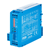
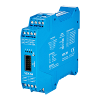
Manual VEK MNE1 / VEK MNE2
14 09/2015 FEIG ELECTRONIC GmbH
GBR
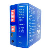
11 Adjustment Options
The adjustments described below are entered either via the associated DIP-switches or via the USB inter-
face using the service program. All main default settings are associated with the DIP-switches. As a rule,
commissioning may be completed without the service program.
The settings entered via the USB interface, can be reset to the factory settings by triggering the basic /
factory settings (see section 10.2).
Legend of the table:
( ) Standard types, as well as the names in the service program Detector tool are specified in brackets
printed on traffic sensors.
DIP Entries in this column show the settings for the DIP-switches
USB Entries in this column indicate values or settings that are possible via the USB interface using the
service program Detector Tool.
Settings entered via the USB interface, which do not match the current DIP-switch positions are indicat-
ed by the blue flashing LED.
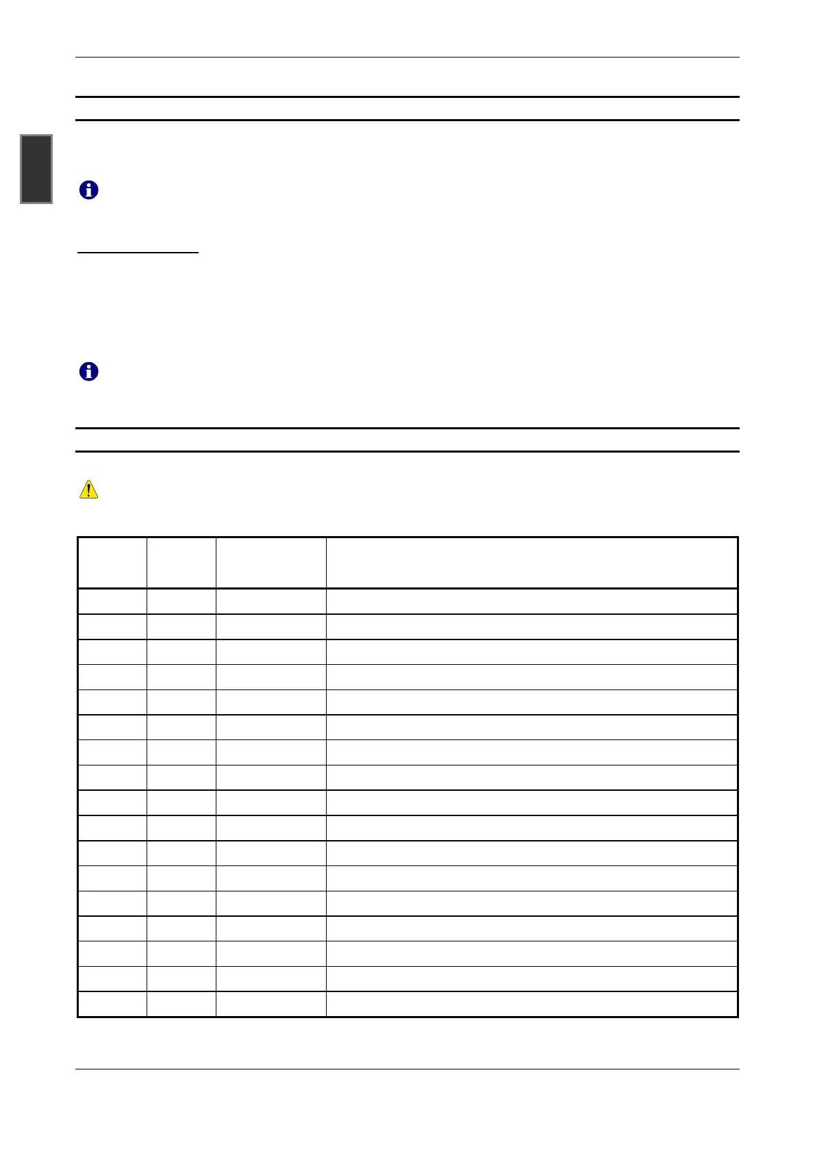
11.1 Sensitivity, On Threshold
In the range of 0.01% - 2.55% ∆f/f the sensitivity of each channel can be selected in 255 steps.
To minimize interference, the sensitivity should only be set as high as necessary. I.e. the response
threshold should be as high as possible.
DIP
Sense a
DIP
Sense b
USB
(response
threshold)
Sensitivity (∆
∆∆
∆f/f)
ON ON 10
0,01 % Stage high Highest sensitivity
20 0,02 %
30 0,03 %
OFF ON 40
0,04 % Stage medium-high
50 0,05 %
:
150 0,15 %
ON OFF 160
0,16 % Stage medium-low
170 0,17 %
:
630 0,63 %
OFF OFF 640
0,64 % Stage low (factory setting)
650 0,65 %
:
1000 1,00 %
:
2550
2,55 % lowest sensitivity
 Loading...