Manual
FEIG ELECTRONIC GmbH
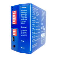
10.4 USB Socket
The USB socket is ava
ilable for extended parameter definitions of the
data using the Detector tool
service program and a commercially available USB cable.
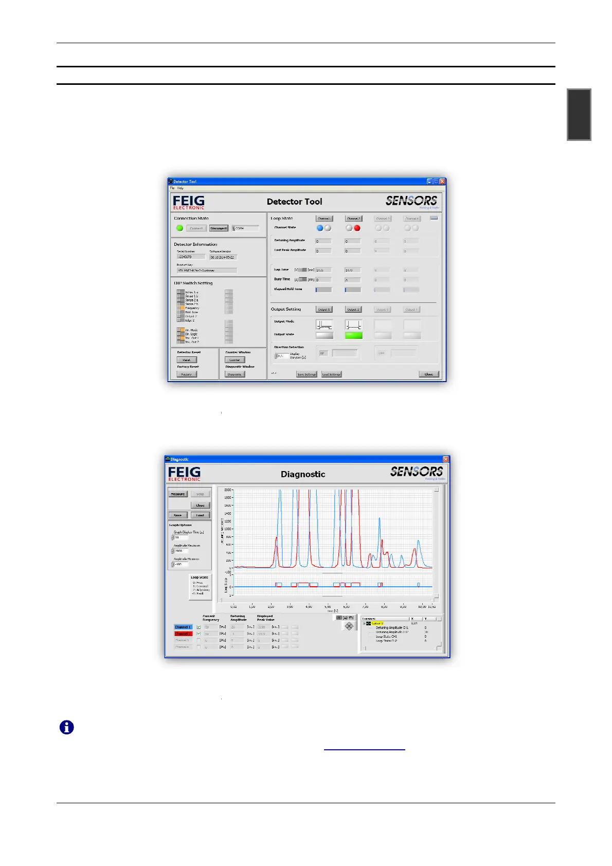
In addition to the settings defined via
time, behavior
under loop errors, output functions, direction detection and activation
lay are possible.
Similarly,
current data such as loop frequency, detuning of the inductive loop, last maximum detuning, last
availability period, time
between two assignments, elapsed hold time, state of the relay output and the d
tected direction of travelling are displayed for the
Time characteristics to detune the inductive loops and relay outputs are displayed in the diagnostic window.
Further information can be found in the separate documentation of the service program
Registered users may
area of the FEIG ELECTRONIC GmbH homepage at
09/2015
ilable for extended parameter definitions of the
sensor
and for the output of diagnostic
service program and a commercially available USB cable.
In addition to the settings defined via
DIP-switches, additional settings for the
under loop errors, output functions, direction detection and activation
current data such as loop frequency, detuning of the inductive loop, last maximum detuning, last
between two assignments, elapsed hold time, state of the relay output and the d
tected direction of travelling are displayed for the
diagnosis.
Time characteristics to detune the inductive loops and relay outputs are displayed in the diagnostic window.
Further information can be found in the separate documentation of the service program
the Detector Tool
service program free of charge from the download
area of the FEIG ELECTRONIC GmbH homepage at
http://www.feig.de.
13
GBR
and for the output of diagnostic
service program and a commercially available USB cable.
off hysteresis, hold
or release delays of re-
current data such as loop frequency, detuning of the inductive loop, last maximum detuning, last
between two assignments, elapsed hold time, state of the relay output and the d
e-
Time characteristics to detune the inductive loops and relay outputs are displayed in the diagnostic window.
Further information can be found in the separate documentation of the service program
Detector Tool.
service program free of charge from the download
 Loading...