Manual VEK MNE1 / VEK MNE2
12 09/2015 FEIG ELECTRONIC GmbH
GBR
10.2 Push Buttons
The following functions are activated by pressing the reset button on the front panel.
Pressing push
button
LED-display
channel 1
Operation
1 s red LED flashes
Triggers a hardware reset with recalibration and resets the LED out-
put for resolved loop faults
5 s blue LED flashes
Triggers default / factory settings
*
Only LEDs on channel 1 are used to display the activation via the push button!
10.3 DIP-switches
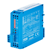
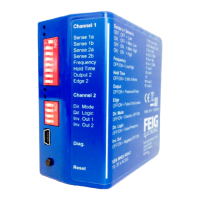
The front of the 1-channel detector VEK MNE1 has an 8-pin DIP-switch to define settings-. For this purpose,
the 2-channel detector VEK MNE2 is equipped with an 8-pin and a 4-pin DIP-switch.
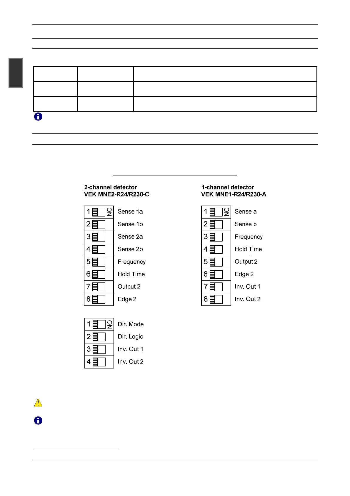
Example of the assignment of the DIP-switches:
The illustrated DIP-switches show the assigned basic functions in the 1- and 2-channel standard variants
VEK MNE1-R24-A, VEK MNE1-R230-A, VEK MNE2-R24-C and VEK MNE2-R230-C that are required for
commissioning,
For other device variants, the DIP-switch assignment may differ from the assignments and arrange-
ments shown above. This is especially true for customized versions!
Additional settings are available via the USB interface using the service program.
*
Settings that are made via the USB interface with the service program are also reset.
 Loading...