Manual VEK MNE1 / VEK MNE2
FEIG ELECTRONIC GmbH 09/2015 5
GBR
3 Functional Description
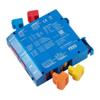
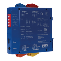
The traffic detectors VEK MNE1 and VEK MNE2 are systems for the inductive recognition of vehicles that
must be installed in control cabinets.
Properties:
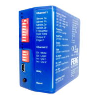
• 1-channel (VEK MNE1) or 2-channel (VEK MNE2) inductive loop detector
• Compact plastic enclosure to be mounted in the control cabinet on sockets on DIN rails
• Automatic adjustment of the system after it is turned on
• Continuous readjustment of frequency drifts to neutralize environmental influences
• Sensitivity independent of loop inductance
• Fixed dwell times regardless of the degree of coverage of loops
• Frequency adjustment
• Direction sensing (only on VEK MNE2)
• Multiplexing method to avoid mutual interference of the loop channels
• LED indication of the loop conditions
• Galvanic isolation between loops and electronics
• Relay outputs
• USB-interface for the diagnosis and other adjustments
Adjustment options:
• Adjustments by means of a 8-pole DIP-switch and a 4-pole DIP-switch (only on VEK MNE2)
• two frequency levels
• Threshold of each channel in 255 steps (via 4 stage DIP-switch)
• Off hysteresis of 20-80% per channel
• Hold time 1-255 minutes and infinite per channel (via DIP-switch 5 minutes and infinite)
• Detector channels can be turned off
• Output adjustable as presence, pulse, direction signal (only on VEK MNE2) or loop failure
3.1 Vehicle Detection System
An LC oscillator determines whether a metallic vehicle is located in the loop region or not. The output of the
channel is controlled in accordance with the selected output function.
3.2 Adjustment
The adjustment of the loop channels is carried out after turning on the detector or by pressing the front but-
ton for about 1 s. After a power failure, an automatic adjustment is carried out only when the operating volt-
age has been interrupted for a period of at least 0.5 s. The adjustment time is approximately 1 s, if the loop is
not crossed by vehicles during this time.
Extended adjustment periods also result by external influences on the loop frequency, their causes must be
identified and eliminated.
3.3 Output Options
Depending on the selected output function, the outputs provide a presence signal, pulse signal, direction
signal (only on VEK MNE2) or loop error. The adjustment of the pulse signal can also be used to select
whether an output takes place when driving on or leaving the loop.
In addition to the inversion of the output signals, both outputs may be turned on or off individually and per-
manently.
3.4 Multiplex-Procedure
The connected induction loops on the 2-channel traffic detector VEK MNE2 are turned on and off in rapid
succession. Current always only flows through one loop. Mutual influence of the loops of a detector is thus
prevented. Both loops connected to a detector can operate at the same frequency.
 Loading...