4
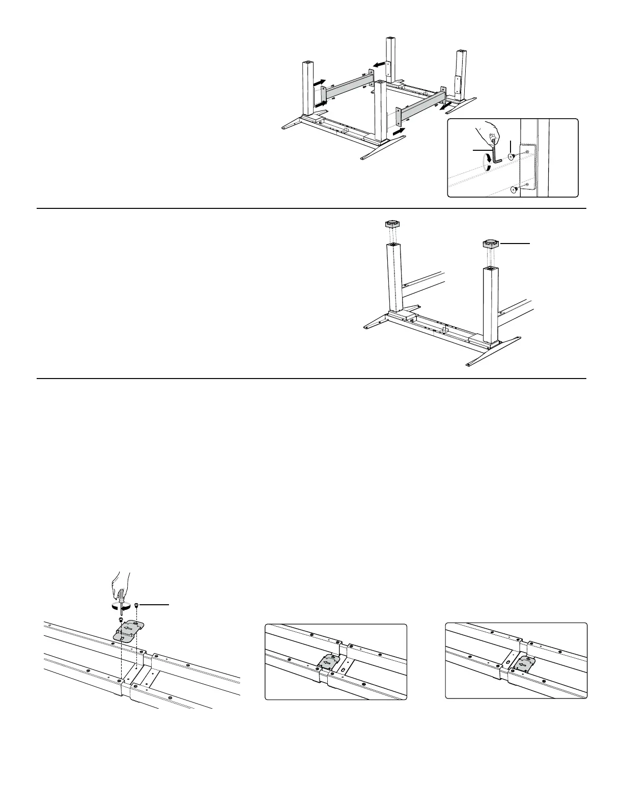
STEP 5
Assemble the feet
t 1MBDFUIFGPPUPOUIFCPUUPNPGUIFMJGUJOHDPMVNO1SFTTUIFGPPU
into the lifting column.
t 3FQFBUUIFTBNFQSPDFTTUPBTTFNCMFUIFPUIFSGFFU
STEP 4
Assembling the Connection Bars
t "MJHOUIFNPVOUJOHIPMFTPOUIFUXPDPOOFDUJPOCBSTXJUIUIF
screw holes on the lifting columns.
t "UUBDI UIF DPOOFDUJPO CBST UP UIF MJGUJOH DPMVNOT VTJOH
countersink Hex Head screws with the Hex Key.
STEP 6
Assemble the fixing plate
t "MJHOUIFNPVOUJOHIPMFTPOUIFGJYJOHQMBUFXJUIUIFTDSFXIPMFTBTTIPXO
t "UUBDIUIFGJYJOHQMBUFPOUIFDFOUFSPGUIFDSPTTCBSXJUI1IJMMJQT)FBETDSFXTVTJOHB1IJMMJQTTDSFXESJWFS5IFGJYJOHQMBUFDBOCFBUUBDIFEUPFJUIFSUIFSJHIU
side or the left side.
t 3FQFBUUIFTBNFQSPDFTTUPBTTFNCMFUIFPUIFSGJYJOHQMBUF
*Note: The arrow on the fixing plate indicates the direction of sliding in the control box. Follow the direction of the arrow to mount the control box in the next step.
OR
G
T
O
D