5
STEP 7
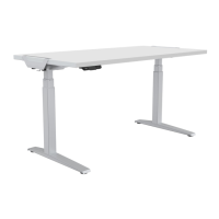
Connecting cords
t $POOFDUUIFUXPNPUPSDPSETUPUIFUXPQPSUTPOFJUIFSTJEFPGUIFDPOUSPMCPYNBSLFE.
BOE.
t $POOFDUUIFDPOUSPMMFSDPSEUPUIFQPSUNBSLFE)4
t *OTFSUUIFQPXFSDPSEJOUIFQPSUNBSLFE"$
t "MJHOUIFGJYJOHQMBUFXJUIUIFSJHIUFOEPGUIFDPOUSPMCPYhTTMPU4MJEFUIFDPOUSPMCPYJOUPUIFGJYJOH
QMBUFGSPNUIFMFGUVOUJMUIFDPOUSPMCPYDBOhUCFNPWFE
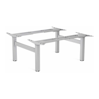
t 3FQFBUUIFTBNFQSPDFTTPOUIFTFDPOEEFTL
*Note: Please make sure the slot on the control box is facing upward. There is no corresponding relation
between the two motor ports and the two lifting columns.
**Note: The picture of the controller is for your reference only. Actual product may vary.
ACCESSORY INSTALLATION - CABLE MANAGEMENT TRAY
Cable management tray
t "MJHOUIFNPVOUJOHIPMFTPOUIFUSBZIBOHFSTXJUIUIF
screw holes on the cable management tray. Assemble
the tray hangers with 4 Phillips Head screws using a
Phillips screwdriver.
t )BOHUIFDBCMFNBOBHFNFOUUSBZPOUIFDSPTTCBS
t 5JHIUFOUIFLOPCTPOUIFUSBZIBOHFST
t 3FQFBUUIFTBNFQSPDFTTUPBTTFNCMFUIFPUIFSDBCMF
management tray.
U
K
J
H
21
C
L