Do you have a question about the Fender 68 Custom Deluxe Reverb and is the answer not in the manual?
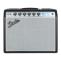
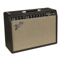
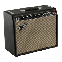
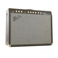
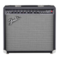
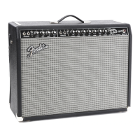
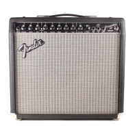
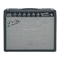
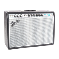
| Type | Tube |
|---|---|
| Output | 22 watts |
| Speaker | 1 x 12" Celestion G12V-70 |
| Reverb | Yes |
| Tremolo | Yes |
| Effects | Reverb, Tremolo |
| Controls | Volume, Treble, Bass, Reverb, Speed, Intensity |
| Inputs | 4 x 1/4" (2 Custom, 2 Vintage) |
| Footswitch | 2-button footswitch included |
| Tubes | 2 x 12AT7, 2 x 6V6 |
| Weight | 42 lbs (19.05 kg) |
| Dimensions | 17.5 x 24.5 x 9.5 inches (44.5 x 62.2 x 24.1 cm) |
| Channels | 2 (Custom and Vintage) |
Details on field serviceability, component-level repair, and contacting Fender for PCB assemblies.
Confidential and proprietary information disclosure terms for Fender Authorized Service Centers.
Note on parts marked with asterisks indicating necessary use for reliability and safety.
Definitions for capacitor, resistor, and hardware codes used in parts lists.
Details on the amplifier model name, release number, and various international part numbers.
Information on power requirements, fuses, input sensitivity, output power, and input impedances.
Specifications for the amplifier's height, width, depth, and total weight.
Step-by-step instructions for safely removing the amplifier chassis from its cabinet.
Policy regarding non-field replaceable PCB assemblies and how to order replacements.
Explanation of new or unusual circuitry designs incorporated into the amplifier model.
Detailed list of components for the Printed Circuit Board (PCB) assembly with part numbers and reference designations.
List of components and assemblies specific to the amplifier's chassis.
Components and assemblies related to the amplifier's cabinet structure and external parts.
List of final product assemblies and associated parts for the amplifier.
Components specific to the footswitch assembly, including the switch and plug.
List of available schematic diagrams for the amplifier's main circuits and PCB.
Schematics specific to the Tremolo circuit and the Solid State Power Supply.