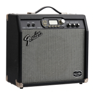
G-DEC
®
Jr
(This is the model name for warranty claims)
5
SERVICE NOTES
1. CHASSIS REMOVAL is accomplished by first
removing the eight (8) screws from the cabinet
back panel. The cabinet back may be removed
by gently prying it out using a flat screwdriver.
Next remove the two (2) screws from the rear
top of the cabinet into the chassis. Last remove
the two (2) handle screws at the cabinet top
that secure the chassis. Disconnect the
speaker wires form the speaker and gently slide
the chassis out from the rear.
2. MAIN PCB REMOVAL is accomplished by first
removing the eleven (11) wires at the Faston®
connectors. There are two wires at P9/P10
(BRN). A set of three (3) wires at P6/P7 (RED)
and P5 (YEL). A set of four (4) mains wires at
P3/P4 (BLK) and P1/P2 (WHT). One (1) ground
wire (GRN) at P5. Remove the two (2) Phillips
head screws that mount the small rear panel
MIDI/AUX/HEADPHONE PCB to the panel.
Remove all nine (9) knobs. Note the four (4)
knobs on the AMP SELECT, FX SELECT, KEY
SELECT and LOOP SELECT encoders are dif-
ferent than the five (5) knobs on the
potentiometers. Keep them separated. Re-
move the panel nut on the INPUT JACK. Pull
the small INPUT PCB down and out of the
chassis hole. Remove the nine (9) panels nuts
and nine (9) flat washers on all the controls.
Remove the two (2) screws that attach the heat
sink to the chassis. Remove the five (5) screws
and five (5) lock washers that attach the PCB to
the chassis standoffs. With the chassis facing
up drop the PCB down until the control shafts
clear the chassis and the slide it back and out
from the chassis. Note that there are two (2)
flat washers on each of the 4 encoders shafts
mentioned above, so do not lose them. To re-
move the heat sink, remove the two (2) sets of
screws, shoulder washers, insulating pads, flat
washers and nuts that secure U3 and U5 to the
heat sink. Last remove the one (1) screw and
one (1) lock washer that holds the heat sink to
the PCB.
PCB EXCHANGE POLICY
Parts marked with a single asterisk (*) in the Part
Lists are not field replaceable. If a failure due to
one of these components is detected, please con-
tact the FMIC Customer Service Department to
order the complete PCB Assembly.